Toyota Venza: Test Mode Procedure
TEST MODE PROCEDURE
1. DESCRIPTION
HINT:
When using a chassis dynamometer, brake tester, etc. to perform a vehicle test, activate test mode to avoid a "different tire diameter installed" incorrect judgment.
Test mode does not have a AWD parameter. Test mode is activated because it will prohibit a different tire diameter judgment.
|
Control Status |
AWD Control Status |
|---|---|
|
During test mode |
Different tire diameter malfunction judgement (detection that tire diameter of all wheels are not same) is not performed. |
2. ACTIVATE TEST MODE
HINT:
Activate test mode before using a chassis dynamometer, brake tester, etc. to perform a vehicle test.
(a) Check that the ignition switch is off.
(b) Use either of the following methods to change the AWD control ECU to test mode.
(1) Test mode activation through the Techstream
- Connect the Techstream to the DLC3 connector and turn the ignition switch to ON. Using the test mode activation function (mode 10), activate test mode.
(2) Test mode activation by shorting the TS terminal
- With the ignition switch off, connect the TS and CG terminals of the
DLC3 connector. Then turn the ignition switch to ON to activate test mode.
NOTICE:
When the ignition switch is turned from off to ON, the AWD warning light will illuminate for 4 seconds. Then it will turn off.
NOTICE:
If a part of the active torque control 4WD system has a defect, the AWD warning light will illuminate.
(c) Check if the AWD warning light has changed to the test mode display.
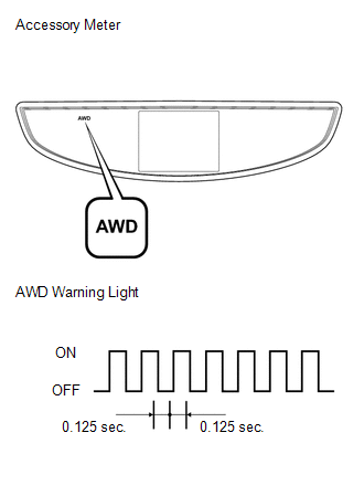
(d) Start the engine.
 Problem Symptoms Table
PROBLEM SYMPTOMS TABLE
HINT:
Use the table below to help determine the cause of problem symptoms.
If multiple suspected areas are listed, the potential causes of the symptoms
are lis ...
 Terminals Of Ecu
TERMINALS OF ECU
1. CHECK AWD CONTROL ECU
(a) Measure the voltage and resistance of the connector.
Terminal No. (Symbol)
Terminal Description
Condition
...
Other materials about Toyota Venza:
CD Sound Skips
PROCEDURE
1.
CHECK CD
(a) Check that the CD is not deformed or cracked.
OK:
No deformation or cracks on the CD.
NG
END (CD IS FAULTY)
...
Diagnostic Trouble Code Chart
DIAGNOSTIC TROUBLE CODE CHART
If a trouble code is displayed during the DTC check, check the trouble areas
listed for that code in the table below and proceed to the appropriate page.
Cruise Control System
DTC Code
Detection Item
...
Relay
On-vehicle Inspection
ON-VEHICLE INSPECTION
PROCEDURE
1. REMOVE STOP LIGHT CONTROL (BRK) RELAY
(a) Remove the stop light control (BRK) relay.
(b) Measure the resistance according to the value(s) in the table below.
Standard Resistance:
...

0.1284