Toyota Venza: Terminals Of Ecu
TERMINALS OF ECU
1. CHECK AWD CONTROL ECU
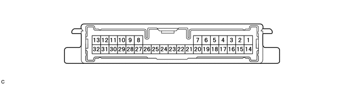
(a) Measure the voltage and resistance of the connector.
|
Terminal No. (Symbol) |
Terminal Description |
Condition |
Specified Condition |
|---|---|---|---|
|
14 (CANH) - 16 (CANL) |
CAN communication |
Ignition switch off |
54 to 69 Ω |
|
23 (GND) - Body ground |
Ground |
Always |
Below 1 Ω |
|
11 (IG1) - 23 (GND) |
Power source voltage |
Ignition switch ON |
10 to 14 V |
|
13 (SLC+) - 32 (SLC-) |
Electromagnetic solenoid signal |
D position, Idling |
Pulse generation (See waveform 1) |
|
9 (BSLC) - 23 (GND) |
Power source voltage |
Always |
10 to 14 V |
If the result is not as specified, the AWD control ECU may have a malfunction.
(b) Using an oscilloscope, check the waveform 1.
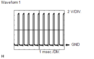 Waveform 1 (Reference)
|
Terminal Name |
Content |
|---|---|
|
Tester Range |
2 V/DIV., 1 msec./DIV. |
|
Condition |
D position, Idling |
 Test Mode Procedure
TEST MODE PROCEDURE
1. DESCRIPTION
HINT:
When using a chassis dynamometer, brake tester, etc. to perform a vehicle test,
activate test mode to avoid a "different tire diameter installed" ...
 Diagnosis System
DIAGNOSIS SYSTEM
1. DESCRIPTION
Active torque control 4WD system data can be read in the Data Link Connector
3 (DLC3) of the vehicle. When the system seems to be malfunctioning, use the Techstream ...
Other materials about Toyota Venza:
ABS Warning Light Remains ON
DESCRIPTION
The skid control ECU is connected to the combination meter via CAN communication.
If any of the following is detected, the ABS warning light remains on:
The skid control ECU connector is disconnected from the skid control
ECU.
The ...
Disassembly
DISASSEMBLY
PROCEDURE
1. REMOVE HOOD TO RADIATOR SUPPORT SEAL
(a) Using a clip remover, disengage the 10 clips and remove the hood
to radiator support seal.
2. REMOVE HOOD INSULATOR
...
Detecting Vehicle Submersion (B2277)
DESCRIPTION
This DTC is stored when the submersion circuit monitor inside the power management
control ECU detects a large amount of water.
DTC No.
DTC Detection Condition
Trouble Area
B2277
The ...

0.1632