Toyota Venza: Diagnosis System
DIAGNOSIS SYSTEM
1. DESCRIPTION
Active torque control 4WD system data can be read in the Data Link Connector 3 (DLC3) of the vehicle. When the system seems to be malfunctioning, use the Techstream to check for malfunctions and perform repairs. Therefore when there seems to be a problem with the active torque control 4WD system, use the Techstream or SST to check and troubleshoot it.
2. CHECK DLC3
(a) The ECU uses CAN (ISO11898-1) and ISO9141-2 for communication protocol. The terminal arrangement of the DLC3 complies with SAE J1962 and matches the ISO9141-2 format.
.png)
Verify the conditions listed in the table below.
|
Symbol (Terminal No.) |
Terminal Description |
Condition |
Specified Condition |
|---|---|---|---|
|
SIL (7) - SG (5) |
Bus + line |
During transmission |
Pulse generation |
|
CG (4) - Body Ground |
Chassis ground |
Always |
Below 1 Ω |
|
SG (5) - Body Ground |
Signal ground |
Always |
Below 1 Ω |
|
BAT (16) - Body Ground |
Battery positive |
Always |
10 to 14 V |
|
CANH (6) - CANL (14) |
CAN bus line |
Ignition switch off* |
54 to 69 Ω |
|
CANH (6) - CG (4) |
HIGH-level CAN bus line |
Ignition switch off* |
200 Ω or higher |
|
CANL (14) - CG (4) |
LOW-level CAN bus line |
Ignition switch off* |
200 Ω or higher |
|
CANH (6) - BAT (16) |
HIGH-level CAN bus line |
Ignition switch off* |
6 kΩ or higher |
|
CANL (14) - BAT (16) |
LOW-level CAN bus line |
Ignition switch off* |
6 kΩ or higher |
NOTICE:
*: Before measuring the resistance, leave the vehicle as is for at least 1 minute and do not operate the ignition switch, other switches or the doors.
If the result is not as specified, the DLC3 may have a malfunction. Repair or replace the harness and connector.
HINT:
Connect the cable of the Techstream to the DLC3, turn the ignition switch to ON and attempt to use the Techstream. If the display indicates that a communication error has occurred, there is a problem either with the vehicle or with the Techstream.
- If communication is normal when the Techstream is connected to another vehicle, inspect the DLC3 of the original vehicle.
- If communication is still not possible when the Techstream is connected to another vehicle, the problem may be in the Techstream itself. Consult the Service Department listed in the Techstream instruction manual.
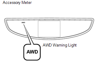
3. WARNING LIGHT
(a) When a problem occurs in the active torque control 4WD system, the AWD warning light on the combination meter comes on to inform the driver of the problem.
 Terminals Of Ecu
TERMINALS OF ECU
1. CHECK AWD CONTROL ECU
(a) Measure the voltage and resistance of the connector.
Terminal No. (Symbol)
Terminal Description
Condition
...
 Dtc Check / Clear
DTC CHECK / CLEAR
1. CHECK DTC (When Using Techstream)
(a) Check the DTCs.
(1) Connect the Techstream to the DLC3.
(2) Turn the ignition switch to ON.
(3) Turn the Techstream on.
(4) Read the DT ...
Other materials about Toyota Venza:
Camshaft Position "A" - Timing Over-Advanced or System Performance (Bank 1)
(P0011,P0012)
DESCRIPTION
Refer to DTC P0010 (See page ).
DTC No.
DTC Detection Condition
Trouble Area
P0011
The valve timing is stuck at a certain value when in the advance range
(1 trip detection logic).
...
Installation
INSTALLATION
CAUTION / NOTICE / HINT
HINT:
Use the same procedure for the RH side and LH side.
The procedure listed below is for the LH side.
PROCEDURE
1. INSTALL FRONT AXLE HUB BEARING
(a) Using SST and a press, install a ne ...
How To Proceed With Troubleshooting
CAUTION / NOTICE / HINT
HINT:
Use the following procedure to troubleshoot the smart key system.
*: Use the Techstream.
PROCEDURE
1.
VEHICLE BROUGHT TO WORKSHOP
NEXT
...

0.1299