Toyota Venza: Installation
INSTALLATION
PROCEDURE
1. INSTALL REAR ENGINE OIL SEAL
(a) Apply MP grease to the lip of a new oil seal.
NOTICE:
- Do not allow foreign matter to contact the lip of the oil seal.
- Do not allow MP grease to contact the dust seal.
|
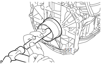
(b) Using SST and a hammer, tap in the oil seal until its surface is flush with the edges of the cylinder block and crankcase. SST: 09223-15030 SST: 09950-70010 09951-07150 NOTICE:
|
|
2. INSTALL DRIVE PLATE AND RING GEAR SUB-ASSEMBLY
|
(a) Using SST, hold the crankshaft. SST: 09213-54015 SST: 09330-00021 HINT: Part number of installation bolt for SST (crankshaft pulley holding tool): 91551-80650 (quantity: 2) |
|
.png)
(b) Clean the bolts and their installation holes.
|
(c) Install the front drive plate spacer. HINT: Align the pin of the front drive plate spacer with the pin hole of the crankshaft. |
|

|
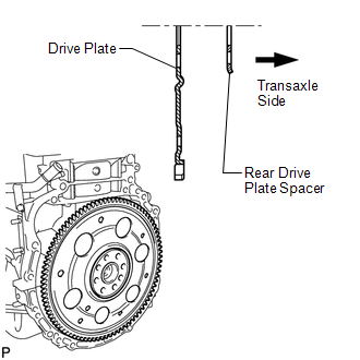
(d) Install the drive plate and rear drive plate spacer to the crankshaft. |
|
|
(e) Apply a few drops of adhesive to 2 or 3 threads of the bolt end. Adhesive: Toyota Genuine Adhesive 1324, Three Bond 1324 or equivalent |
|
.png)
|
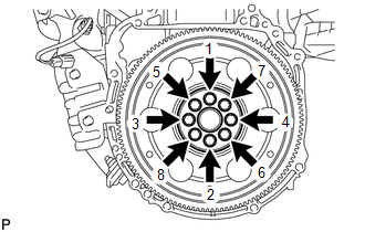
(f) Install and uniformly tighten the 8 bolts in the sequence shown in the illustration. Torque: 98 N·m {999 kgf·cm, 72 ft·lbf} NOTICE: Do not strike or damage the drive plate installation bolts. Be sure to handle them carefully. |
|
3. INSTALL AUTOMATIC TRANSAXLE ASSEMBLY (for 2WD)
When Not Using the Engine Support Bridge: (See page
.gif) )
)
When Using the Engine Support Bridge: (See page
)
4. INSTALL AUTOMATIC TRANSAXLE ASSEMBLY (for AWD)
When Not Using the Engine Support Bridge: (See page
)
When Using the Engine Support Bridge: (See page
)
 Removal
REMOVAL
PROCEDURE
1. REMOVE AUTOMATIC TRANSAXLE ASSEMBLY (for 2WD)
When Not Using the Engine Support Bridge: (See page
)
When Using the Engine Support Bridge: (See page
)
2. REMOVE AUTOMATIC ...
 1ar-fe Fuel
...
Other materials about Toyota Venza:
System Description
SYSTEM DESCRIPTION
1. DESCRIPTION OF SYSTEM
(a) Each tire pressure warning valve and transmitter is equipped with a tire
pressure sensor and a transmitter and is installed in each tire and wheel assembly.
The sensor measures the tire pressure. The measur ...
Insufficient Coolant Temperature for Closed Loop Fuel Control (P0125)
DESCRIPTION
Refer to DTC P0115 (See page ).
DTC No.
DTC Detection Condition
Trouble Area
P0125
The engine coolant temperature does not reach the closed loop enabling
temperature for 20 minutes ...
Maintenance requirements
To ensure safe and economical driving, day-to-day care and regular maintenance
is essential. It is the owner’s responsibility to perform regular checks. Toyota
recommends the following maintenance.
- General maintenance
Should be performed on a d ...

0.1257