Toyota Venza: Terminals Of Ecu
TERMINALS OF ECU
1. CLEARANCE WARNING ECU ASSEMBLY

(a) Disconnect the D79 clearance warning ECU assembly connector.
(b) Measure the voltage and resistance according to the value(s) in the table below.
|
Terminal No. (Symbol) |
Wiring Color |
Terminal Description |
Condition |
Specified Condition |
|---|---|---|---|---|
|
D79-9 (CLSW) - D79-30 (E) |
B - W |
Back sonar or clearance sonar switch assembly power source signal |
Engine switch on (IG), clearance sonar main switch on |
11 to 14 V |
|
D79-9 (CLSW) - D79-30 (E) |
B - W |
Back sonar or clearance sonar switch assembly power source signal |
Engine switch on (IG), clearance sonar main switch off |
Below 1 V |
|
D79-1 (IG) - D79-30 (E) |
GR - W |
IG power source signal |
Engine switch off |
Below 1 V |
|
Engine switch on (IG) |
11 to 14 V |
|||
|
D79-30 (E) - Body ground |
W - Body ground |
Ground |
Always |
Below 1 Ω |
(c) Reconnect the D79 clearance warning ECU assembly connector.
(d) Measure the voltage and check for pulses according to the value(s) in the table below.
|
Terminal No. (Symbol) |
Wiring Color |
Terminal Description |
Condition |
Specified Condition |
|---|---|---|---|---|
|
D79-22 (BOR) - D79-30 (E) |
V - W |
Power source for rear sensor circuit |
Engine switch off |
Below 1 V |
|
Engine switch on (IG), clearance sonar main switch on |
7.2 to 8.8 V |
|||
|
D79-8 (SOF) - D79-30 (E) |
LG - W |
Front sensor communication signal (Front clearance sonar sensor) |
Engine switch on (IG), clearance sonar main switch on, shift lever in R |
Pulse generation (See waveform 2) |
|
D79-13 (ER) - D79-30 (E) |
Y - W |
Clearance warning buzzer signal |
Buzzer sounding |
Pulse generation (See waveform 1) |
|
D79-23 (E1) - D79-30 (E) |
L - W |
Ground for rear clearance sonar |
Always |
Below 1 V |
|
D79-6 (E5) - D79-30 (E) |
BR - W |
Ground for front clearance sonar |
Always |
Below 1 V |
|
D79-4 (BOF) - D79-30 (E) |
W - W |
Power source for front sensor circuit |
Engine switch off |
Below 1 V |
|
Engine switch on (IG), clearance sonar main switch on |
7.2 to 8.8 V |
|||
|
D79-24 (SOR) - D79-30 (E) |
Y - W |
Rear sensor communication signal (Rear clearance sonar sensor) |
Engine switch on (IG), clearance sonar main switch on, shift lever in R |
Pulse generation (See waveform 2) |
(e) Using an oscilloscope, check waveform 1.
(1) Waveform 1 (Reference)
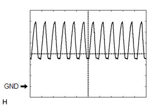
|
Item |
Content |
|---|---|
|
Terminal No. (Symbol) |
D79-13 (ER) - D79-30 (E) |
|
Tool Setting |
2 V/DIV., 500 μsec./DIV. |
|
Vehicle Condition |
When sonar detects obstacle (buzzer sounds) |
|
Buzzer volume |
Buzzer sounding |
HINT:
The amplitude of the waveform changes according to the set volume.
(f) Using an oscilloscope, check waveform 2.
(1) Waveform 2 (Reference)
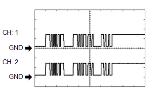
|
Item |
Content |
|---|---|
|
Terminal No. (Symbol) |
|
|
Tool Setting |
5 V/DIV., 1 msec./DIV. |
|
Condition |
Engine switch on (IG), clearance sonar main switch on, shift lever in R |
HINT:
The waveforms for CH1 and CH2 are same.
 Problem Symptoms Table
PROBLEM SYMPTOMS TABLE
HINT:
Use the table below to help determine the cause of problem symptoms.
If multiple suspected areas are listed, the potential causes of the symptoms
are lis ...
 Diagnosis System
DIAGNOSIS SYSTEM
1. DESCRIPTION
(a) When troubleshooting a vehicle with a diagnosis system, the only difference
from the usual troubleshooting procedure is connecting the Techstream to the vehicle ...
Other materials about Toyota Venza:
Low Battery Positive Voltage or Abnormally High Battery Positive Voltage (C1241/41)
DESCRIPTION
If a malfunction is detected in the power supply circuit, the skid control ECU
(housed in the actuator assembly) stores this DTC and the fail-safe function prohibits
ABS operation.
This DTC is stored when the IG1 terminal voltage deviates fro ...
Removal
REMOVAL
PROCEDURE
1. REMOVE AUTOMATIC TRANSAXLE ASSEMBLY
HINT:
See the steps from "Remove Engine Assembly with transaxle" through "Remove Automatic
Transaxle Assembly" (See page ).
2. REMOVE AUTOMATIC TRANSAXLE OIL PAN SUB-ASSEMBLY
...
Reassembly
REASSEMBLY
PROCEDURE
1. PRECAUTION
NOTICE:
After turning the ignition switch off, waiting time may be required before disconnecting
the cable from the negative (-) battery terminal. Therefore, make sure to read the
disconnecting the cable from the nega ...

0.1498