Toyota Venza: Starting the engine
 Shift the shift lever to “P” and
apply the brakes.
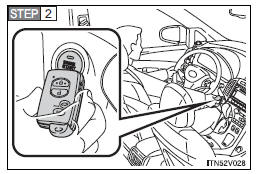
Touch the Toyota emblem side of the electronic key to the “ENGINE START STOP” switch.
An alarm will sound to indicate that the start function cannot detect the electronic key that is touched to the “ENGINE START STOP” switch if any of the doors is opened and closed while the key is touched to the switch.
 Press the “ENGINE START STOP” switch
within 10 seconds after the buzzer sounds, keeping the brake pedal depressed.
In the event that the “ENGINE START STOP” switch cannot be operated, contact your Toyota dealer.
- Stopping the engine
Shift the shift lever to “P” and press the “ENGINE START STOP” switch as you normally do when stopping the engine.
- Replacing the key battery
As this above procedure is a temporary measure, it is recommended that the electronic key battery be replaced immediately when the battery depletes.
- Alarm
Using the mechanical key to lock the doors will not set the alarm system.
If a door is unlocked using the mechanical key when the alarm system is set, the alarm may be triggered. - Changing “ENGINE START STOP” switch mode
Release the brake pedal and press the “ENGINE START STOP” switch in
 above.
The engine does not start
and modes will be changed each time the switch is pressed.
 Locking and unlocking the doors and key linked functions
Using the mechanical key in order to perform the following operations.
1. Locks all doors
2. Unlocks all doors
Turning the key rearward unlocks the driver’s door. Turning the key once again
w ...
 If the battery is discharged
The following procedures may be used to start the engine if the battery is
discharged.
You can call your Toyota dealer or qualified repair shop.
If you have a set of jumper (or booster) cables and ...
Other materials about Toyota Venza:
Removal
REMOVAL
PROCEDURE
1. REMOVE FRONT SEAT HEADREST ASSEMBLY
2. REMOVE FRONT SEAT REAR OUTER TRACK COVER
3. REMOVE FRONT SEAT REAR INNER TRACK COVER
4. REMOVE FRONT SEAT ASSEMBLY
5. REMOVE SLIDE AND VERTICAL POWER SEAT SWITCH KNOB
6. REMOVE RECL ...
System Diagram
SYSTEM DIAGRAM
Communication Table
Sender
Receiver
Signal
Line
ECM
Navigation Receiver Assembly*1
Radio and Display Receiver Assembly*2
Reverse sig ...
Screen Flicker or Color Distortion
PROCEDURE
1.
CHECK DISPLAY SETTING
(a) Reset display settings (contrast, brightness) and check that the screen appears
normal.
OK:
The display returns to normal.
OK
END
NG
...

0.1217