Toyota Venza: Terminals Of Ecu
TERMINALS OF ECU
HINT:
Check from the rear of the connector while it is connected to the components.
1. RADIO AND DISPLAY RECEIVER ASSEMBLY

|
Terminal No. (Symbol) |
Wiring Color |
Terminal Description |
Condition |
Specified Condition |
|---|---|---|---|---|
|
E4-1 (FR+) - E4-7 (GND1) |
LG - BR |
Sound signal (Front right) |
Audio system playing |
A waveform synchronized with sound signals is output |
|
E4-2 (FL+) - E4-7 (GND1) |
P - BR |
Sound signal (Front left) |
Audio system playing |
A waveform synchronized with sound signals is output |
|
E4-3 (ACC1) - E4-7 (GND1) |
GR - BR |
Power source (ACC) |
Ignition switch off |
Below 1 V |
|
Ignition switch ACC |
11 to 14 V |
|||
|
E4-4 (+B1) - E4-7 (GND1) |
SB - BR |
Power source (+B) |
Always |
11 to 14 V |
|
E4-5 (FR-) - E4-7 (GND1) |
L - BR |
Sound signal (Front right) |
Audio system playing |
A waveform synchronized with sound signals is output |
|
E4-6 (FL-) - E4-7 (GND1) |
V - BR |
Sound signal (Front left) |
Audio system playing |
A waveform synchronized with sound signals is output |
|
E4-7 (GND1) - Body ground |
BR - Body ground |
Ground |
Always |
Below 1 V |
|
E4-10 (ILL+) - E4-7 (GND1) |
G - BR |
Illumination signal |
Light control switch off |
Below 1 V |
|
Light control switch in tail or head position |
11 to 14 V |
|||
|
E5-1 (RR+) - E4-7 (GND1) |
R - BR |
Sound signal (Rear right) |
Audio system playing |
A waveform synchronized with sound signals is output |
|
E5-2 (RL+) - E4-7 (GND1) |
B - BR |
Sound signal (Rear left) |
Audio system playing |
A waveform synchronized with sound signals is output |
|
E5-3 (RR-) - E4-7 (GND1) |
W - BR |
Sound signal (Rear right) |
Audio system playing |
A waveform synchronized with sound signals is output |
|
E5-5 (ILL-) - E4-7 (GND1) |
W - BR |
Illumination signal |
Light control switch off |
Below 1 V |
|
Light control switch in tail or head position |
Pulse generation |
|||
|
E5-6 (RL-) - E4-7 (GND1) |
Y - BR |
Sound signal (Rear left) |
Audio system playing |
A waveform synchronized with sound signals is output |
|
E42-1 (IG) - E4-7 (GND1) |
V - BR |
Power source (IG) |
Ignition switch off |
Below 1 V |
|
Ignition switch ON |
11 to 14 V |
|||
|
E42-4 (MACC) - E4-7 (GND1) |
R - BR |
Microphone power supply |
Ignition switch off |
Below 1 V |
|
Ignition switch ACC |
4 to 6 V |
|||
|
E42-5 (MIN+) - E4-7 (GND1) |
B - BR |
Microphone voice signal |
See "Check Microphone" in Operation Check (See page
|
- |
|
E42-6 (SNS2) - E4-7 (GND1) |
Y - BR |
Microphone connection detection signal |
Always |
Below 1 V |
|
E42-9 (CANH) |
SB |
CAN communication signal |
- |
- |
|
E42-10 (CANL) |
W |
CAN communication signal |
- |
- |
|
E42-11 (AGND) - Body ground |
Shield - Body ground |
Shield ground |
Always |
Below 1 V |
|
E42-15 (PKB) - E4-7 (GND1) |
R - BR |
Parking brake signal |
See "Check Vehicle Signal" in Operation Check (See page
|
- |
|
E42-17 (SPD) - E4-7 (GND1) |
BR - BR |
Vehicle speed signal |
See "Check Vehicle Signal" in Operation Check (See page
|
- |
|
E42-18 (SGND) - Body ground |
Shield - Body ground |
Shield ground |
Always |
Below 1 V |
|
E42-19 (MIN-) - E4-7 (GND1) |
W - BR |
Microphone voice signal |
See "Check Microphone" in Operation Check (See page
|
- |
|
E42-21 (SW1) - E42-23 (SWG) |
GR - R |
Steering pad switch signal |
No switch pushed |
2.97 to 3.56 V |
|
Up switch pushed |
0.27 to 0.35 V |
|||
|
Down switch pushed |
0.86 to 1.03 V |
|||
|
Volume+ switch pushed |
1.51 to 1.79 V |
|||
|
Volume- switch pushed |
2.22 to 2.66 V |
|||
|
E42-22 (SW2) - E42-23 (SWG) |
LG - R |
Steering pad switch signal |
No switch pushed |
2.97 to 3.56 V |
|
MODE/HOLD switch pushed |
0.27 to 0.35 V |
|||
|
On hook switch pushed |
0.86 to 1.03 V |
|||
|
Off hook switch pushed |
1.51 to 1.79 V |
|||
|
Voice switch pushed |
2.22 to 2.66 V |
|||
|
E42-23 (SWG) - E4-7 (GND1) |
R - BR |
Steering pad switch ground |
Always |
Below 1 V |
|
E42-24 (SW3) - E42-23 (SWG) |
L - R |
Steering pad switch signal |
No switch pushed |
2.97 to 3.56 V |
|
Enter switch pushed |
0.27 to 0.35 V |
|||
|
Back switch pushed |
0.86 to 1.03 V |
|||
|
Right switch pushed |
1.51 to 1.79 V |
|||
|
Left switch pushed |
2.22 to 2.66 V |
|||
|
E42-25 (ADPG) - E4-7 (GND1) |
SB - BR |
External device connection detection signal |
External device connected |
Below 1 V |
|
External device not connected |
2.1 to 3 V |
|||
|
E42-26 (VAR+) - E42-27 (VA-) |
B - W |
Sound signal (Right) |
External device playing (When stereo jack used) |
A waveform synchronized with sound signals is output |
|
E42-27 (VA-) - E4-7 (GND1) |
W - BR |
Ground |
Always |
Below 1 V |
|
E42-28 (VAL+) - E42-27 (VA-) |
B - W |
Sound signal (Left) |
External device playing (When stereo jack used) |
A waveform synchronized with sound signals is output |
|
E52-11 (CA+) - E4-7 (GND1)*1 |
B - BR |
Television camera power supply |
Ignition switch ACC |
5.5 to 7.05 V |
|
E52-12 (V+) - E4-7 (GND1)*1 |
R - BR |
Video signal |
Ignition switch ON Shift lever in R Camera lens not covered, displaying an image |
Pulse generation (Refer to waveform 1) |
|
Ignition switch ON Shift lever in R Camera lens covered, blacking out screen |
Pulse generation (Refer to waveform 2) |
|||
|
E52-23 (CGND) - Body ground*1 |
Shield - Body ground |
Shield ground |
Always |
Below 1 V |
|
E52-24 (V-) - E4-7 (GND1)*1 |
W - BR |
Ground |
Always |
Below 1 V |
|
V2-3 (ACC2) - E4-7 (GND1)*2 |
Y - BR |
Power source (ACC) |
Ignition switch off |
Below 1 V |
|
Ignition switch ACC |
11 to 14 V |
|||
|
V2-4 (+B2) - E4-7 (GND1)*2 |
R - BR |
Power source (+B) |
Always |
11 to 14 V |
|
V2-8 (GND2) - Body ground*2 |
B - Body ground |
Ground |
Always |
Below 1 V |
|
E48-1 (UPO) |
- |
Power source |
- |
- |
|
E48-2 (UDO-) |
- |
Data signal |
- |
- |
|
E48-3 (UDO+) |
- |
Data signal |
- |
- |
|
E48-4 (UESG) |
- |
Ground |
- |
- |
|
E48-5 (USG1) |
- |
Shield ground |
- |
- |
|
V6-1 (USV4)*2 |
- |
Power source |
- |
- |
|
V6-2 (US4-)*2 |
- |
Data signal |
- |
- |
|
V6-3 (US4+)*2 |
- |
Data signal |
- |
- |
|
V6-4 (UGD4)*2 |
- |
Ground |
- |
- |
|
V6-5 (USG4)*2 |
- |
Shield ground |
- |
- |
|
V4-1 (LV1)*2 |
- |
LVDS communication signal |
- |
- |
|
RA-5 (ANT+) - E4-7 (GND1) |
- - BR |
Power source of antenna |
Ignition switch ACC Radio switch on and FM or AM selected |
11 to 14 V |
.gif) )
)- *1: w/ Rear View Monitor System
- *2: w/ SDARS System
(a) Reference (Oscilloscope waveform):
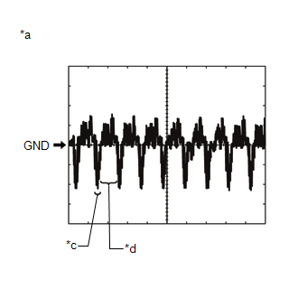
(1) Waveform 1 (camera lens not covered, displaying an image)
|
Item |
Content |
|---|---|
|
Measurement terminal |
E52-12 (V+) - E4-7 (GND1) |
|
Measurement setting |
200 mV/DIV., 50 μs./DIV. |
|
Condition |
Ignition switch ON, shift lever in R |
HINT:
- The video waveform changes according to the image sent by the rear television camera assembly.
- The video waveform is constantly output when the ignition switch is ACC.
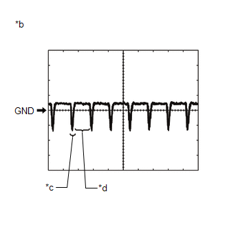
(2) Waveform 2 (camera lens covered, blacking out the screen)
|
Item |
Content |
|---|---|
|
Measurement terminal |
E52-12 (V+) - E4-7 (GND1) |
|
Measurement setting |
200 mV/DIV., 50 μs./DIV. |
|
Condition |
Ignition switch ON, shift lever in R |
HINT:
- The video waveform changes according to the image sent by the rear television camera assembly.
- The video waveform is constantly output when the ignition switch is ACC.
|
*a |
Waveform 1 (camera lens not covered, displaying an image) |
|
*b |
Waveform 2 (camera lens covered, blacking out the screen) |
|
*c |
Synchronization Signal |
|
*d |
Video Waveform |
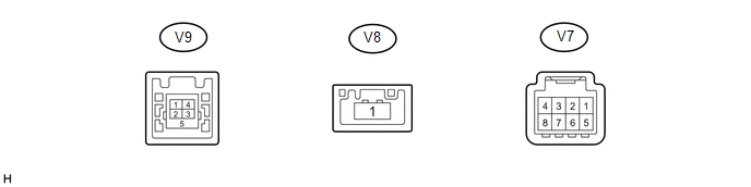
2. STEREO COMPONENT TUNER ASSEMBLY (w/ SDARS System)
|
Terminal No. (Symbol) |
Wiring Color |
Terminal Description |
Condition |
Specified Condition |
|---|---|---|---|---|
|
V7-3 (ACC2) - V7-8 (GND2) |
Y - B |
Power source (ACC) |
Ignition switch off |
Below 1 V |
|
Ignition switch ACC |
11 to 14 V |
|||
|
V7-4 (+B2) - V7-8 (GND2) |
R - B |
Power source (+B) |
Always |
11 to 14 V |
|
V7-8 (GND2) - Body ground |
B - Body ground |
Ground |
Always |
Below 1 V |
|
V9-1 (USV4) |
- |
Power source |
- |
- |
|
V9-2 (US4-) |
- |
Data signal |
- |
- |
|
V9-3 (US4+) |
- |
Data signal |
- |
- |
|
V9-4 (UGD4) |
- |
Ground |
- |
- |
|
V9-5 (USG4) |
- |
Shield ground |
- |
- |
|
V8-1 (LV1) |
- |
LVDS communication signal |
- |
- |
 Problem Symptoms Table
PROBLEM SYMPTOMS TABLE
NOTICE:
After replacing the stereo component tuner assembly of vehicles subscribed to
pay-type satellite radio broadcasts, XM radio ID registration is necessary (w/ SDARS
...
 Dtc Check / Clear
DTC CHECK / CLEAR
1. CHECK DTC (CHECK USING TECHSTREAM)
(a) Connect the Techstream to the DLC3.
(b) Turn the ignition switch to ON.
(c) Turn the Techstream on.
(d) Enter the following menus: Body ...
Other materials about Toyota Venza:
Reassembly
REASSEMBLY
PROCEDURE
1. INSTALL NO. 1 INSTRUMENT PANEL PIN
(a) Install the 2 No. 1 instrument panel pins with the 2 screws <E> or
<F>.
2. INSTALL GLOVE BOX LIGHT ASSEMBLY
...
Installation
INSTALLATION
PROCEDURE
1. INSTALL REAR DOOR BELT MOULDING
(a) Engage the 5 claws to install the rear door belt moulding.
2. INSTALL REAR DOOR GLASS SUB-ASSEMBLY
3. INSTALL REAR DOOR WINDOW DIVIS ...
Lost Communication with Clearance Warning ECU (U1110)
DESCRIPTION
DTC Code
DTC Detection Condition
Trouble Area
U1110
No communication from the clearance warning ECU assembly continues.
Clearance warning ECU assembly branch wire o ...

0.1183