Toyota Venza: Reassembly
REASSEMBLY
PROCEDURE
1. INSTALL GENERATOR ROTOR ASSEMBLY
(a) Place the drive end frame on the clutch pulley.
|
(b) Install the generator rotor assembly to the drive end frame. |
|
.png)
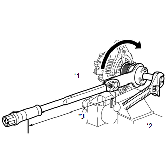
2. INSTALL GENERATOR CLUTCH PULLEY
(a) Temporarily install the clutch pulley onto the rotor shaft.
(b) Mount the generator drive end frame in a vise tightly.
|
(c) Confirm SST (A) and (B) shown in the illustration. Text in Illustration
SST: 09820-63021 |
|
.png)
|
(d) Place the rotor shaft end into SST (A). Text in Illustration
|
|
.png)
|
(e) Fit SST (B) to the clutch pulley. Text in Illustration
|
|
.png)
|
(f) Tighten the pulley by turning SST (B) in the direction shown in the illustration. Text in Illustration
Torque: without SST : 80 N·m {816 kgf·cm, 59 ft·lbf} with SST : 64 N·m {653 kgf·cm, 47 ft·lbf} NOTICE:
|
|
(g) Remove SST from the generator assembly.
(h) Check that the clutch pulley rotates smoothly.
(i) Install a new clutch pulley cap to the clutch pulley.
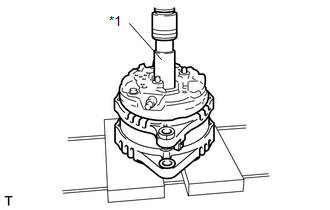
3. INSTALL GENERATOR COIL ASSEMBLY
|
(a) Place a new generator washer on the generator rotor. |
|
.png)
|
(b) Using a deep socket wrench (21 mm) and a press, slowly press in the generator coil assembly. Text in Illustration
|
|
|
(c) Install the 4 bolts. Torque: 5.9 N·m {60 kgf·cm, 52 in·lbf} |
|
.png)
4. INSTALL GENERATOR BRUSH HOLDER ASSEMBLY
|
(a) While pushing the 2 brushes into the generator brush holder assembly, insert a 1.0 mm (0.0394 in.) pin into the brush holder hole. Text in Illustration
|
|
.png)
|
(b) Install the brush holder assembly to the generator coil with the 2 screws. Torque: 1.8 N·m {18 kgf·cm, 16 in·lbf} |
|
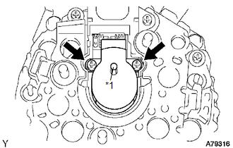
(c) Pull out the pin from the generator brush holder.
Text in Illustration|
*1 |
Pin |
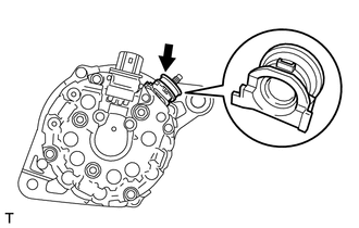
5. INSTALL TERMINAL INSULATOR
|
(a) Install the terminal insulator to the generator coil. NOTICE: Be sure to install the terminal insulator in the correct direction. |
|
6. INSTALL GENERATOR REAR END COVER
|
(a) Install the generator rear end cover to the generator coil with the 3 nuts. Torque: 4.6 N·m {47 kgf·cm, 41 in·lbf} |
|
.png)
 Installation
INSTALLATION
PROCEDURE
1. INSTALL GENERATOR ASSEMBLY
(a) Install the wire harness clamp with the bolt.
Torque:
8.4 N·m {86 kgf·cm, 74 in·lbf}
...
 Networking
...
Other materials about Toyota Venza:
Rocker Panel Moulding
Components
COMPONENTS
ILLUSTRATION
Removal
REMOVAL
PROCEDURE
1. REMOVE FRONT FENDER OUTSIDE MOULDING
2. REMOVE NO. 2 ROCKER PANEL MOULDING PROTECTOR
3. REMOVE REAR ROCKER PANEL MOULDING END COVER
4. REMOVE BODY ROCKER PANEL MOULDING ASS ...
Open in Inside Luggage Compartment Electrical Key Oscillator Circuit (B27A7)
DESCRIPTION
The certification ECU (smart key ECU assembly) generates a request signal and
sends it to the indoor electrical key oscillator (for rear floor). To detect the
key inside the cabin, the indoor electrical key oscillator (for rear floor) creates ...
Interior lights list
Your Toyota is equipped with the illuminated entry system to assist in entering
the vehicle. Due to the function of the system, the lights shown in the following
illustration automatically turn on/off according to the presence of the electronic
key (vehi ...

0.1491