Toyota Venza: Removal
REMOVAL
CAUTION / NOTICE / HINT
NOTICE:
w/Camera mirror:The timing of the change between high beams and low beams differs depending on the light transmission rate of the glass. For this reason, when replacing the windshield, replace it with an original equipment part.
PROCEDURE
1. REMOVE FRONT WIPER ARM HEAD CAP
.gif)
2. REMOVE FRONT WIPER ARM AND BLADE ASSEMBLY LH
3. REMOVE FRONT WIPER ARM AND BLADE ASSEMBLY RH
4. REMOVE FRONT FENDER TO COWL SIDE SEAL LH
5. REMOVE FRONT FENDER TO COWL SIDE SEAL RH
6. REMOVE COWL TOP VENTILATOR LOUVER SUB-ASSEMBLY
7. DISCONNECT FRONT DOOR OPENING TRIM WEATHERSTRIP LH
(a) Remove the front part of the front door opening trim weatherstrip to the extent that allows removal of the front pillar garnish.
8. REMOVE FRONT PILLAR GARNISH LH
9. DISCONNECT FRONT DOOR OPENING TRIM WEATHERSTRIP RH
(a) Remove the front part of the front door opening trim weatherstrip to the extent that allows removal of the front pillar garnish.
10. REMOVE FRONT PILLAR GARNISH RH
HINT:
Use the same procedure for the RH side and the LH side.
11. REMOVE INNER REAR VIEW MIRROR STAY HOLDER COVER
12. REMOVE INNER REAR VIEW MIRROR ASSEMBLY (w/o Automatic High Beam System)
13. REMOVE INNER REAR VIEW MIRROR ASSEMBLY (w/ Automatic High Beam System)
14. REMOVE MAP LIGHT ASSEMBLY (ROOF CONSOLE BOX ASSEMBLY)
15. REMOVE VISOR BRACKET COVER (for LH Side)
16. REMOVE VISOR ASSEMBLY LH
17. REMOVE VISOR BRACKET COVER (for RH Side)
HINT:
Use the same procedure for the RH side and the LH side.
18. REMOVE VISOR ASSEMBLY RH
HINT:
Use the same procedure for the RH side and the LH side.
19. REMOVE ASSIST GRIP SUB-ASSEMBLY (w/o Sliding Roof)
20. REMOVE ASSIST GRIP SUB-ASSEMBLY (w/ Sliding Roof)
21. REMOVE VISOR HOLDER
22. REMOVE ROOF HEADLINING ASSEMBLY
(a) Slightly lower the front section of the roof headlining assembly so that the windshield glass can be removed.
HINT:
It is not necessary to completely remove the roof headlining assembly.
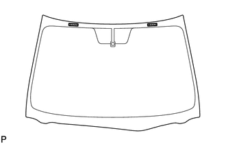
23. REMOVE WINDSHIELD GLASS
|
(a) Disconnect the connector. (w/ Deicer) |
|
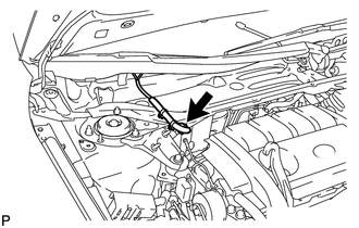
|
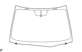
(b) Apply protective tape to the installation position of the windshield glass on the vehicle body. Text in Illustration
HINT: Apply protective tape to the installation surface to prevent it from being scratched. |
|
|
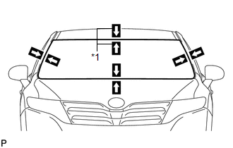
(c) Pass a piano wire between the vehicle body and glass from the interior, as shown in the illustration. HINT: Do not allow the piano wire to interfere with the clips. Text in Illustration
|
|
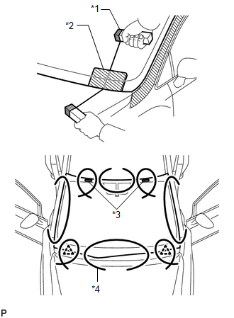
(d) Tie both wire ends to wooden blocks or similar objects that can serve as handles.
(e) Cut off the adhesive by pulling the piano wire around the windshield glass.
NOTICE:
- When separating the windshield glass, be careful not to damage the paint or the interior and exterior ornaments.
- To prevent the safety pad from being scratched when removing the windshield glass, place a plastic sheet between the piano wire and safety pad.
|
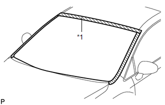
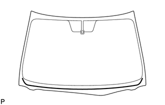
(f) Place matchmarks on the windshield glass and vehicle body on the locations indicated in the illustration. Text in Illustration
HINT: Matchmarks are not necessary if the windshield glass is not going to be reused. |
|
|
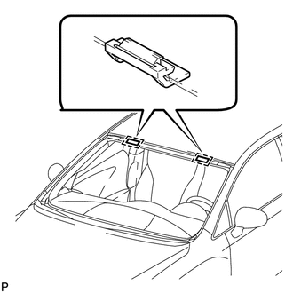
(g) Disconnect the 2 guides. |
|
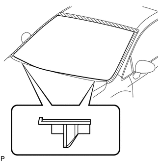
(h) Disconnect the windshield glass stoppers.
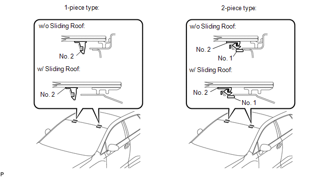
NOTICE:
- There are No. 1 and No. 2 stoppers on the windshield glass as shown in the illustration.
- To prevent the windshield glass from dropping when performing this operation, be sure to hold the windshield glass using suction cups.
HINT:
Depending on vehicles, 1-piece or 2-piece type stoppers are used.
(i) Using suction cups, remove the windshield glass.
NOTICE:
- Be careful not to drop the windshield glass.
- Leave as much adhesive on the vehicle body as possible when removing the windshield glass.
24. REMOVE WINDOW GLASS ADHESIVE DAM
|
(a) Using a scraper, remove the window glass adhesive dam. NOTICE:
|
|
25. REMOVE WINDSHIELD GLASS RETAINER
|
(a) Using a scraper, remove the 2 windshield glass retainers. NOTICE: Be careful not to damage the windshield glass. |
|
26. REMOVE NO. 2 WINDSHIELD GLASS STOPPER
|
(a) Using a scraper, remove the 2 No. 2 windshield glass stoppers. NOTICE:
|
|
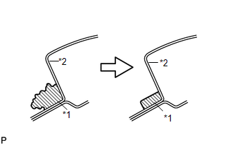
27. REMOVE NO. 1 WINDSHIELD GLASS STOPPER (for 2-piece Type)
|
(a) Remove the 2 No. 1 windshield glass stoppers as shown in the illustration. |
|
28. CLEAN WINDSHIELD GLASS
|
(a) Using a scraper, remove the adhesive tape and adhesive sticking to the windshield glass. NOTICE: Be careful not to damage the windshield glass. |
|
(b) Clean the outer circumference of the windshield glass with a non-residue solvent.
NOTICE:
- Do not touch the windshield glass surface after cleaning it.
- Even if using a new windshield glass, clean the windshield glass with a non-residue solvent.
29. CLEAN VEHICLE BODY
|
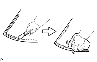
(a) Clean and shape the contact surfaces of the vehicle body. (1) Using a knife, cut away excess adhesive on the contact surfaces of the vehicle body, as shown in the illustration. Text in Illustration
NOTICE: Be careful not to damage the vehicle body. HINT: Leave as much adhesive on the vehicle body as possible. (2) Clean the contact surfaces of the vehicle body with a piece of cloth saturated with cleaner. HINT: Even if all the adhesive has been removed, clean the vehicle body. |
|
 Components
COMPONENTS
ILLUSTRATION
ILLUSTRATION
ILLUSTRATION
ILLUSTRATION
ILLUSTRATION
...
 Installation
INSTALLATION
PROCEDURE
1. INSTALL NO. 2 WINDSHIELD GLASS STOPPER
(a) Using a brush or a sponge, coat the application area of 2 new No. 2 windshield
glass stoppers with Primer G.
NOTICE:
...
Other materials about Toyota Venza:
Driving position memory
Your preferred driving position (the position of the driver’s seat and angle
of the outside rear view mirrors) can be memorized and recalled by pressing a button.
It is also possible to set this function to activate automatically when the doors
are unl ...
Checking and replacing fuses
If any of the electrical components do not operate, a fuse may have blown.
If this happens, check and replace the fuses as necessary.
Vehicles with smart key system:
Turn the “ENGINE START STOP” switch off.
Vehicles without smart key system:
Turn th ...
System Description
SYSTEM DESCRIPTION
1. FRONT POWER SEAT CONTROL SYSTEM DESCRIPTION
The driver seat is equipped with slide, reclining, lifter, front vertical and
lumbar support adjustment functions.
2. FUNCTION OF MAIN COMPONENTS
The following functions are available:
...

0.1454