Toyota Venza: Front Lower Suspension Arm(when Using The Engine Support Bridge)
Components
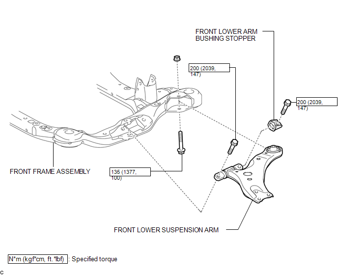
COMPONENTS
ILLUSTRATION
Removal
REMOVAL
CAUTION / NOTICE / HINT
HINT:
- Use the same procedure for the LH side and RH side.
- The following procedure is for the LH side.
PROCEDURE
1. REMOVE FRONT FRAME ASSEMBLY
for 1AR-FE: (See page .gif) )
)
for 2GR-FE: (See page )
2. REMOVE FRONT LOWER SUSPENSION ARM
|
(a) Remove the 3 bolts, nut and front lower suspension arm from the front frame assembly. |
|
.png)
(b) Remove the front lower arm bushing stopper from the front lower suspension arm.
Installation
INSTALLATION
CAUTION / NOTICE / HINT
HINT:
- Use the same procedure for the LH side and RH side.
- The following procedure is for the LH side.
PROCEDURE
1. INSTALL FRONT LOWER SUSPENSION ARM
(a) Install the front lower arm bushing stopper to the front lower suspension arm.
(b) Temporarily tighten the front lower suspension arm to the front frame assembly with the 3 bolts and nut.
|
(c) Tighten the 3 bolts in the order shown in the illustration. Torque: Bolt 1, 2 : 200 N·m {2039 kgf·cm, 147 ft·lbf} Bolt 3 : 135 N·m {1377 kgf·cm, 100 ft·lbf} HINT: Start installing the bolts from the front of the vehicle. |
|
.png)
2. INSTALL FRONT FRAME ASSEMBLY
for 1AR-FE: (See page .gif) )
)
for 2GR-FE: (See page )
 Installation
INSTALLATION
CAUTION / NOTICE / HINT
HINT:
Use the same procedure for the LH side and RH side.
The following procedure is for the LH side.
PROCEDURE
1. INSTALL FRONT LOWER SUSPE ...

Other materials about Toyota Venza:
Disassembly
DISASSEMBLY
CAUTION / NOTICE / HINT
HINT:
Use an overhaul stand as necessary.
PROCEDURE
1. REMOVE REAR DIFFERENTIAL FILLER PLUG
(a) Remove the rear differential filler plug and gasket.
2. INSPECT ...
Automatic High Beam Mirror (B124A)
DESCRIPTION
The DTC is stored when the main body ECU (driver side junction block assembly)
detects malfunctions in the inner rear view mirror assembly.
DTC No.
DTC Detection Condition
Trouble Area
B124A
...
Power Back Door cannot be Closed Using the Power Back Door Closer Switch
DESCRIPTION
When the power back door cannot be closed using the power back door closer switch,
either of the following may be malfunctioning: 1) power back door closer switch
circuit or 2) power back door ECU (power back door motor unit).
WIRING DIAGRAM
...

0.1266