Toyota Venza: Terminals Of Ecm
TERMINALS OF ECM
HINT:
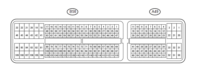
The standard voltage between each pair of ECM terminals is shown in the table below. The appropriate conditions for checking each pair of terminals are also indicated. The result of checks should be compared with the standard voltage for that pair of terminals, displayed in the Specified Condition column. The illustration above can be used as a reference to identify the ECM terminal locations.
|
Terminal No. (Symbol) |
Wiring Color |
Terminal Description |
Condition |
Specified Condition |
|---|---|---|---|---|
|
A49-20 (BATT) - B58-104 (E1) |
V - BR |
Battery (for measuring battery voltage and for ECM memory) |
Always |
11 to 14 V |
|
A49-3 (+BM) - B58-104 (E1) |
BR - BR |
Power source of throttle actuator |
Always |
11 to 14 V |
|
A49-28 (IGSW) - B58-104 (E1) |
SB - BR |
Ignition switch |
Ignition switch ON |
11 to 14 V |
|
A49-2 (+B) - B58-104 (E1) |
R - BR |
Power source of ECM |
Ignition switch ON |
11 to 14 V |
|
A49-1 (+B2) - B58-104 (E1) |
GR - BR |
Power source of ECM |
Ignition switch ON |
11 to 14 V |
|
B58-36 (OC1+) - B58-59 (OC1-) |
L-R - G-B |
Camshaft timing oil control valve assembly for intake camshaft |
Idling |
Pulse generation (see waveform 1) |
|
A49-6 (MREL) - B58-104 (E1) |
P - BR |
EFI MAIN relay |
Ignition switch ON |
11 to 14 V |
|
B58-94 (VG) - B58-117 (E2G) |
R - L-W |
Mass air flow meter |
Idling, shift lever in P or N, A/C switch off |
0.5 to 3.0 V |
|
B58-116 (THA) - B58-93 (ETHA) |
L-B - W-B |
Intake air temperature sensor (built into mass air flow meter) |
Idling, intake air temperature 20°C (68°F) |
0.5 to 3.4 V |
|
B58-64 (THW) - B58-65 (ETHW) |
G-B - B |
Engine coolant temperature sensor |
Idling, engine coolant temperature 80°C (176°F) |
0.2 to 1.0 V |
|
B58-88 (VCTA) - B58-111 (ETA) |
Y-B - W-B |
Power source of throttle position sensor (specific voltage) |
Ignition switch ON |
4.5 to 5.5 V |
|
B58-90 (VTA1) - B58-111 (ETA) |
R-W - W-B |
Throttle position sensor (for engine control) |
Ignition switch ON, accelerator pedal fully released |
0.5 to 1.1 V |
|
Ignition switch ON, accelerator pedal fully depressed |
3.2 to 4.8 V |
|||
|
B58-89 (VTA2) - B58-111 (ETA) |
B-R - W-B |
Throttle position sensor (for sensor malfunction detection) |
Ignition switch ON, accelerator pedal fully released |
2.1 to 3.1 V |
|
Ignition switch ON, accelerator pedal fully depressed |
4.6 to 5.0 V |
|||
|
A49-55 (VPA) - A49-59 (EPA) |
L - GR |
Accelerator pedal position sensor (for engine control) |
Ignition switch ON, accelerator pedal fully released |
0.5 to 1.1 V |
|
Ignition switch ON, accelerator pedal fully depressed |
2.6 to 4.5 V |
|||
|
A49-56 (VPA2) - A49-60 (EPA2) |
BE - LG |
Accelerator pedal position sensor (for sensor malfunction detection) |
Ignition switch ON, accelerator pedal fully released |
1.2 to 2.0 V |
|
Ignition switch ON, accelerator pedal fully depressed |
3.4 to 4.75 V |
|||
|
A49-57 (VCPA) - A49-59 (EPA) |
G - GR |
Power source of accelerator pedal position sensor (for VPA) |
Ignition switch ON |
4.5 to 5.5 V |
|
A49-58 (VCP2) - A49-60 (EPA2) |
Y - LG |
Power source of accelerator pedal position sensor (for VPA2) |
Ignition switch ON |
4.5 to 5.5 V |
|
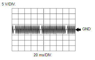
B58-18 (HA1A) - B58-46 (E04) |
BR - W-B |
Air fuel ratio sensor heater |
Idling |
Pulse generation (see waveform 2) |
|
Ignition switch ON |
11 to 14 V |
|||
|
B58-103 (A1A+) - B58-104 (E1) |
P - BR |
Air fuel ratio sensor |
Ignition switch ON |
3.3 V*1 |
|
B58-126 (A1A-) - B58-104 (E1) |
L - BR |
Air fuel ratio sensor |
Ignition switch ON |
2.9 V*1 |
|
B58-41 (HT1B) - B58-86 (E03) |
Y - B |
Heated oxygen sensor heater |
Ignition switch ON |
11 to 14 V |
|
B58-125 (OX1B) - B58-102 (O1B-) |
G - R |
Heated oxygen sensor |
Engine speed maintained at 2500 rpm for 2 minutes after warming up engine |
Pulse generation (see waveform 3) |
|
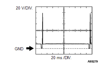
B58-85 (#10) - B58-109 (E01) B58-84 (#20) - B58-109 (E01) B58-83 (#30) - B58-109 (E01) B58-82 (#40) - B58-109 (E01) |
G - W Y - W R - W L-R - W |
Fuel injector |
Ignition switch ON |
11 to 14 V |
|
Idling |
Pulse generation (see waveform 4) |
|||
|
B58-87 (KNK1) - B58-110 (EKNK) |
R - G |
Knock sensor |
Engine speed maintained at 4000 rpm after warming up engine |
Pulse generation (see waveform 5) |
|
B58-76 (G2+) - B58-122 (G2-) |
P - V |
Camshaft position sensor for intake camshaft |
Idling |
Pulse generation (see waveform 7) |
|
B58-74 (NE+) - B58-120 (NE-) |
R - G |
Crankshaft position sensor |
Idling |
Pulse generation (see waveform 6) |
|
A49-53 (NEO)*2 - B58-104 (E1) |
GR - BR |
Crankshaft position sensor |
Idling with warm engine |
Pulse generation (see waveform 18) |
|
B58-108 (IGT1) - B58-104 (E1) B58-107 (IGT2) - B58-104 (E1) B58-106 (IGT3) - B58-104 (E1) B58-105 (IGT4) - B58-104 (E1) |
R-L - BR P - BR Y-B - BR L-Y - BR |
Ignition coil (ignition signal) |
Idling |
Pulse generation (see waveform 8) |
|
B58-23 (IGF1) - B58-104 (E1) |
W-R - BR |
Ignition coil (ignition confirmation signal) |
Ignition switch ON |
4.5 to 5.5 V |
|
Idling |
Pulse generation (see waveform 8) |
|||
|
B58-28 (PRG) - B58-104 (E1) |
G - BR |
Purge VSV |
Ignition switch ON |
11 to 14 V |
|
Idling, under purge control |
Pulse generation (see waveform 9) |
|||
|
A49-15 (SPD) - B58-104 (E1) |
BR - BR |
Speed signal from combination meter |
Vehicle driven at 20 km/h (12 mph) |
Pulse generation (see waveform 10) |
|
A49-48 (STA) - B58-104 (E1) |
BR - BR |
Starter signal |
Cranking |
6 V or higher |
|
B58-47 (NSW) - B58-104 (E1) |
G - BR |
Park/neutral position switch signal |
Ignition switch ON, shift lever in P or N |
Below 3.0 V |
|
Ignition switch ON, shift lever not in P or N |
11 to 14 V |
|||
|
A49-29 (STP) - B58-104 (E1) |
G - BR |
Stop light switch assembly |
Brake pedal depressed |
7.5 to 14 V |
|
Brake pedal released |
Below 1.5 V |
|||
|
A49-39 (ST1-) - B58-104 (E1) |
V - BR |
Stop light switch assembly (opposite to voltage at STP terminal) |
Ignition switch ON, brake pedal depressed |
Below 1.5 V |
|
Ignition switch ON, brake pedal released |
7.5 to 14 V |
|||
|
B58-21 (M+) - B58-19 (ME01) |
Y - B |
Throttle actuator |
Idling with warm engine |
Pulse generation (see waveform 11) |
|
B58-20 (M-) - B58-19 (ME01) |
L - B |
Throttle actuator |
Idling with warm engine |
Pulse generation (see waveform 12) |
|
A49-8 (FC) - B58-104 (E1) |
LG - BR |
Fuel pump control |
Ignition switch ON |
11 to 14 V |
|
Idling |
Below 1.5 V |
|||
|
A49-36 (W) - B58-104 (E1) |
R - BR |
MIL |
Ignition switch ON (MIL turns on) |
Below 1.5 V |
|
Idling |
11 to 14 V |
|||
|
A49-7 (TC) - B58-104 (E1) |
V - BR |
Terminal TC of DLC3 |
Ignition switch ON |
11 to 14 V |
|
A49-26 (TACH) - B58-104 (E1) |
Y - BR |
Engine speed |
Idling |
Pulse generation (see waveform 13) |
|
A49-42 (VPMP) - B58-104 (E1) |
BE - BR |
Vent valve (built into canister pump module) |
Ignition switch ON |
11 to 14 V |
|
A49-34 (MPMP) - B58-104 (E1) |
V - BR |
Leak detection pump (built into canister pump module) |
Leak detection pump OFF |
Below 3 V |
|
Leak detection pump ON |
9 to 14 V |
|||
|
B58-113 (VCPP) - B58-112 (EPPM) |
LG - W |
Power source for canister pressure sensor (specific voltage) |
Ignition switch ON |
4.5 to 5.5 V |
|
B58-114 (PPMP) - B58-112 (EPPM) |
Y - W |
Canister pressure sensor (built into canister pump module) |
Ignition switch ON |
3.0 to 3.6 V |
|
A49-21 (FANL) - B58-104 (E1) |
L - BR |
FAN NO. 3 relay |
Ignition switch ON |
Below 1.5 V |
|
Idling with A/C ON, or high engine coolant temperature |
||||
|
A49-22 (FANH) - B58-104 (E1) |
P - BR |
FAN NO. 1 and FAN NO. 2 relay |
Idling with high engine coolant temperature |
Below 1.5 V |
|
B58-39 (ALT) - B58-104 (E1) |
L - BR |
Generator |
Ignition switch ON |
11 to 14 V |
|
A49-13 (CANH) - B58-104 (E1) |
Y - BR |
CAN communication line |
Ignition switch ON |
Pulse generation (see waveform 14) |
|
A49-5 (CANL) - B58-104 (E1) |
W - BR |
CAN communication line |
Ignition switch ON |
Pulse generation (see waveform 15) |
|
B58-27 (ACIS) - B58-104 (E1) |
R-Y - BR |
VSV for Acoustic Control Induction System (ACIS) operation signal |
Ignition switch ON |
11 to 14 V |
|
B58-35 (OE1+) - B58-58 (OE1-) |
G - GR |
Camshaft timing oil control valve assembly for exhaust camshaft |
Idling |
Pulse generation (see waveform 1) |
|
B58-99 (VCV1) - B58-104 (E1) |
LG - BR |
Power source of camshaft position sensor for intake camshaft (specific voltage) |
Ignition switch ON |
4.5 to 5.5 V |
|
B58-98 (VCE1) - B58-104 (E1) |
BR - BR |
Power source of camshaft position sensor for exhaust camshaft (specific voltage) |
Ignition switch ON |
4.5 to 5.5 V |
|
B58-75 (EV1+) - B58-121 (EV1-) |
Y - BR |
Camshaft position sensor for exhaust camshaft |
Idling |
Pulse generation (see waveform 7) |
|
B58-4 (IA1+) - B58-109 (E01) |
BR - W |
DC motor for tumble control valve |
Idling with cold engine |
Pulse generation (see waveform 16) |
|
B58-3 (IA1-) - B58-109 (E01) |
LG - W |
DC motor for tumble control valve |
Idling with cold engine |
Pulse generation (see waveform 17) |
|
B58-70 (IAC1) - B58-71 (EIA1) |
R-W - B-R |
Tumble control valve position sensor |
Ignition switch ON |
3.0 to 4.0 V |
|
B58-72 (VCIA) - B58-104 (E1) |
W-L - BR |
Power source of tumble control valve position sensor (specific voltage) |
Ignition switch ON |
4.5 to 5.5 V |
|
B58-24 (CAN+) - B58-104 (E1) |
R - BR |
CAN communication line |
Ignition switch ON |
Pulse generation (see waveform 14) |
|
B58-1 (CAN-) - B58-104 (E1) |
W - BR |
CAN communication line |
Ignition switch ON |
Pulse generation (see waveform 15) |
|
A49-12 (CANP)*2 - B58-104 (E1) |
G - BR |
CAN communication line |
Ignition switch ON |
Pulse generation (see waveform 14) |
|
A49-4 (CANN)*2 - B58-104 (E1) |
W - BR |
CAN communication line |
Ignition switch ON |
Pulse generation (see waveform 15) |
|
A49-16 (SFTU) - B58-104 (E1) |
R - BR |
Up shift switch signal |
Ignition switch ON and shift lever in S |
11 to 14 V |
|
Ignition switch ON and shift lever in S, the "+" range (up shift) selected |
Below 1 V |
|||
|
A49-51 (SFTD) - B58-104 (E1) |
LG - BR |
Down shift switch signal |
Ignition switch ON and shift lever in S |
11 to 14 V |
|
Ignition switch ON and shift lever in S, the "-" range (down shift) selected |
Below 1 V |
|||
|
B58-32 (P) - B58-104 (E1) |
Y - BR |
P shift position switch signal |
Ignition switch ON and shift lever in P |
11 to 14 V |
|
Ignition switch ON and shift lever in any position other than P |
Below 1 V |
|||
|
B58-33 (R) - B58-104 (E1) |
V - BR |
R shift position switch signal |
Ignition switch ON and shift lever in R |
11 to 14 V |
|
Ignition switch ON and shift lever in any position other than R |
Below 1 V |
|||
|
B58-34 (N) - B58-104 (E1) |
L-B - BR |
N shift position switch signal |
Ignition switch ON and shift lever in N |
11 to 14 V |
|
Ignition switch ON and shift lever in any position other than N |
Below 1 V |
|||
|
B58-30 (D) - B58-104 (E1) |
BR - BR |
D shift position switch signal |
Ignition switch ON and shift lever in D |
11 to 14 V |
|
Ignition switch ON and shift lever in any position other than D |
Below 1 V |
|||
|
A49-14 (S) - B58-104 (E1) |
BE - BR |
S shift position switch signal |
Ignition switch ON and shift lever in S |
11 to 14 V |
|
Ignition switch ON and shift lever in any position other than S |
Below 1 V |
- *1: The ECM terminal voltage is constant regardless of the output voltage shown on the Techstream.
- *2: w/ Smart Key System
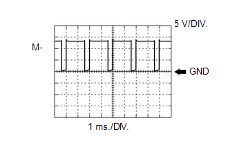
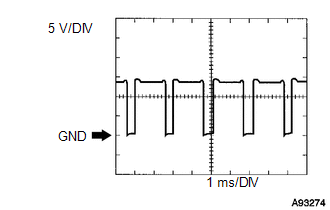
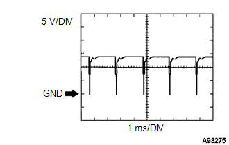
1. WAVEFORM 1
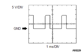 Camshaft Timing Oil Control Valve
Assembly Signal
|
Terminal No. (Symbol) |
Tool Setting |
Condition |
|---|---|---|
|
B58-36 (OC1+) - B58-59 (OC1-) |
5 V/DIV, 1 ms/DIV |
Idling |
|
B58-35 (OE1+) - B58-58 (OE1-) |
5 V/DIV, 1 ms/DIV |
Idling |
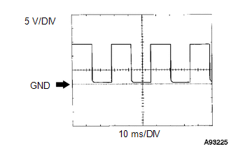
2. WAVEFORM 2
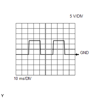 Air Fuel Ratio Sensor (Bank 1 Sensor
1) Heater Signal
|
Terminal No. (Symbol) |
Tool Setting |
Condition |
|---|---|---|
|
B58-18 (HA1A) - B58-46 (E04) |
5 V/DIV, 10 ms/DIV |
Idling |
3. WAVEFORM 3
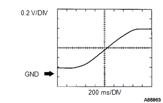 Heated Oxygen Sensor (Bank 1 Sensor
2) Signal
|
Terminal No. (Symbol) |
Tool Setting |
Condition |
|---|---|---|
|
B58-125 (OX1B) - B58-102 (O1B-) |
0.2 V/DIV, 200 ms/DIV |
Engine speed maintained at 2500 rpm for 2 minutes after warming up engine |
HINT:
In the Data List, item O2S B1S2 shows the ECM input values from the heated oxygen sensor.
4. WAVEFORM 4
 Injector No. 1 (to No. 4) Injection
Signal
|
Terminal No. (Symbol) |
Tool Setting |
Condition |
|---|---|---|
|
B58-85 (#10) - B58-109 (E01) |
20 V/DIV, 20 ms/DIV |
Idling |
|
B58-84 (#20) - B58-109 (E01) |
20 V/DIV, 20 ms/DIV |
Idling |
|
B58-83 (#30) - B58-109 (E01) |
20 V/DIV, 20 ms/DIV |
Idling |
|
B58-82 (#40) - B58-109 (E01) |
20 V/DIV, 20 ms/DIV |
Idling |
HINT:
The wavelength becomes shorter as the engine speed increases.
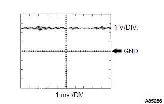
5. WAVEFORM 5
 Knock Sensor Signal
|
Terminal No. (Symbol) |
Tool Setting |
Condition |
|---|---|---|
|
B58-87 (KNK1) - B58-110 (EKNK) |
1 V/DIV, 1 ms/DIV |
Engine speed maintained at 4000 rpm after warming up engine |
HINT:
- The wavelength becomes shorter as the engine speed increases.
- The waveforms and amplitudes displayed differ slightly depending on the vehicle.
6. WAVEFORM 6
 Crankshaft Position Sensor Signal
|
Terminal No. (Symbol) |
Tool Setting |
Condition |
|---|---|---|
|
B58-74 (NE+) - B58-120 (NE-) |
5 V/DIV, 20 ms/DIV |
Idling |
HINT:
The wavelength becomes shorter as the engine speed increases.
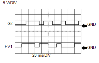
7. WAVEFORM 7
 Camshaft Position Sensor Signal
|
Terminal No. (Symbol) |
Tool Setting |
Condition |
|---|---|---|
|
B58-76 (G2+) - B58-122 (G2-) |
5 V/DIV, 20 ms/DIV |
Idling |
|
B58-75 (EV1+) - B58-121 (EV1-) |
5 V/DIV, 20 ms/DIV |
Idling |
HINT:
The wavelength becomes shorter as the engine speed increases.
8. WAVEFORM 8
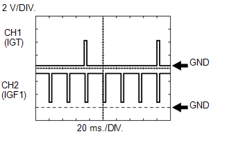 Ignition Coil IGT Signal (from ECM
to Ignition Coil) and Ignition Coil IGF Signal (from Ignition Coil to ECM)
|
Terminal No. (Symbol) |
Tool Setting |
Condition |
|---|---|---|
|
B58-108 (IGT1) - B58-104 (E1) |
2 V/DIV, 20 ms/DIV |
Idling |
|
B58-107 (IGT2) - B58-104 (E1) |
2 V/DIV, 20 ms/DIV |
Idling |
|
B58-106 (IGT3) - B58-104 (E1) |
2 V/DIV, 20 ms/DIV |
Idling |
|
B58-105 (IGT4) - B58-104 (E1) |
2 V/DIV, 20 ms/DIV |
Idling |
|
B58-23 (IGF1) - B58-104 (E1) |
2 V/DIV, 20 ms/DIV |
Idling |
HINT:
The wavelength becomes shorter as the engine speed increases.
9. WAVEFORM 9
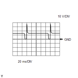 Purge VSV Signal
|
Terminal No. (Symbol) |
Tool Setting |
Condition |
|---|---|---|
|
B58-28 (PRG) - B58-104 (E1) |
10 V/DIV, 20 ms/DIV |
Idling, under purge control |
HINT:
If the waveform is not similar to the illustration, check the waveform again after idling for 10 minutes or more.
10. WAVEFORM 10
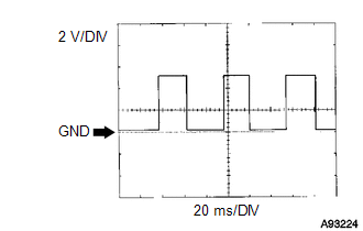 Vehicle Speed Signal
|
Terminal No. (Symbol) |
Tool Setting |
Condition |
|---|---|---|
|
A49-15 (SPD) - B58-104 (E1) |
2 V/DIV, 20 ms/DIV |
Vehicle driven at 20 km/h (12 mph) |
HINT:
The wavelength becomes shorter as the vehicle speed increases.
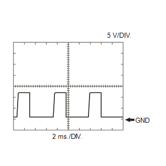
11. WAVEFORM 11
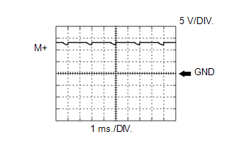 Throttle Actuator Positive Terminal
Signal
|
Terminal No. (Symbol) |
Tool Setting |
Condition |
|---|---|---|
|
B58-21 (M+) - B58-19 (ME01) |
5 V/DIV, 1 ms/DIV |
Idling with warm engine |
HINT:
The duty ratio varies depending on the throttle actuator operation.
12. WAVEFORM 12
 Throttle Actuator Negative Terminal
Signal
|
Terminal No. (Symbol) |
Tool Setting |
Condition |
|---|---|---|
|
B58-20 (M-) - B58-19 (ME01) |
5 V/DIV, 1 ms/DIV |
Idling with warm engine |
HINT:
The duty ratio varies depending on the throttle actuator operation.
13. WAVEFORM 13
 Engine Speed Signal
|
Terminal No. (Symbol) |
Tool Setting |
Condition |
|---|---|---|
|
A49-26 (TACH) - B58-104 (E1) |
5 V/DIV, 10 ms/DIV |
Idling |
HINT:
The wavelength becomes shorter as the engine speed increases.
14. WAVEFORM 14
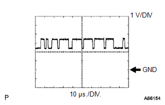 CAN Communication Signal (Reference)
|
Terminal No. (Symbol) |
Tool Setting |
Condition |
|---|---|---|
|
A49-13 (CANH) - B58-104 (E1) |
1 V/DIV, 10 μs/DIV |
Ignition switch ON |
|
B58-24 (CAN+) - B58-104 (E1) |
1 V/DIV, 10 μs/DIV |
Ignition switch ON |
|
A49-12 (CANP) - B58-104 (E1) |
1 V/DIV, 10 μs/DIV |
Ignition switch ON |
HINT:
The waveform varies depending on the CAN communication signal.
15. WAVEFORM 15
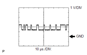 CAN Communication Signal (Reference)
|
Terminal No. (Symbol) |
Tool Setting |
Condition |
|---|---|---|
|
A49-5 (CANL) - B58-104 (E1) |
1 V/DIV, 10 μs/DIV |
Ignition switch ON |
|
B58-1 (CAN-) - B58-104 (E1) |
1 V/DIV, 10 μs/DIV |
Ignition switch ON |
|
A49-4 (CANN) - B58-104 (E1) |
1 V/DIV, 10 μs/DIV |
Ignition switch ON |
HINT:
The waveform varies depending on the CAN communication signal.
16. WAVEFORM 16
 DC Motor for Tumble Control Valve
Positive Terminal Signal
|
Terminal No. (Symbol) |
Tool Setting |
Condition |
|---|---|---|
|
B58-4 (IA1+) - B58-109 (E01) |
5 V/DIV, 1 ms/DIV |
Idling with cold engine |
17. WAVEFORM 17
 DC Motor for Tumble Control Valve
Negative Terminal Signal
|
Terminal No. (Symbol) |
Tool Setting |
Condition |
|---|---|---|
|
B58-3 (IA1-) - B58-109 (E01) |
5 V/DIV, 1 ms/DIV |
Idling with cold engine |
18. WAVEFORM 18
 Crankshaft Position Sensor Signal
|
Terminal No. (Symbol) |
Tool Setting |
Condition |
|---|---|---|
|
A49-53 (NEO) - B58-104 (E1) |
5 V/DIV, 2 ms/DIV |
Idling with warm engine |
 Readiness Monitor Drive Pattern
READINESS MONITOR DRIVE PATTERN
1. PURPOSE OF READINESS TESTS
The On-Board Diagnostic (OBD II) system is designed to monitor the performance
of emission related components, and indicate a ...
 Diagnosis System
DIAGNOSIS SYSTEM
1. DESCRIPTION
When troubleshooting OBD II (On-Board Diagnostics) vehicles, an OBD
II scan tool (complying with SAE J1987) must be connected to the DLC3 (Data
Link Co ...
Other materials about Toyota Venza:
Removal
REMOVAL
CAUTION / NOTICE / HINT
HINT:
Use the same procedure for the RH side and LH side.
The procedure listed below is for the LH side.
PROCEDURE
1. REMOVE REAR POWER WINDOW REGULATOR SWITCH ASSEMBLY WITH REAR DOOR ARMREST
BASE PANEL
...
Power Source Control ECU Malfunction (B2782)
DESCRIPTION
The power management control ECU controls the power supply to activate the steering
lock motor. This prevents the steering wheel from being locked while the vehicle
is moving.
DTC No.
DTC Detecting Condition
T ...
Inspection
INSPECTION
PROCEDURE
1. INSPECT TIE ROD ASSEMBLY LH
(a) Secure the tie rod assembly LH in a vise.
(b) Install the nut to the stud bolt.
(c) Flip the ball joint back and forth 5 times.
(d) Set a to ...

0.1748