Toyota Venza: Air Conditioning Pressure Sensor
Components
COMPONENTS
ILLUSTRATION
Installation
INSTALLATION
PROCEDURE
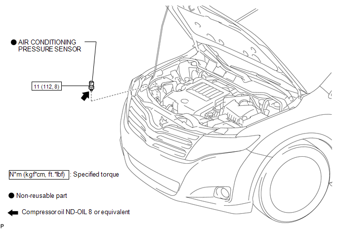
1. INSTALL AIR CONDITIONING PRESSURE SENSOR
|
(a) Sufficiently apply compressor oil to a new air conditioning pressure sensor. Compressor oil: ND-OIL 8 or equivalent |
|
(b) Install the air conditioning pressure sensor.
Torque:
11 N·m {112 kgf·cm, 8 ft·lbf}
(c) Connect the connector.
2. CONNECT CABLE TO NEGATIVE BATTERY TERMINAL
NOTICE:
When disconnecting the cable, some systems need to be initialized after the cable
is reconnected (See page .gif) ).
).
3. CHARGE WITH REFRIGERANT
4. WARM UP ENGINE
5. INSPECT FOR REFRIGERANT LEAK
Removal
REMOVAL
PROCEDURE
1. RECOVER REFRIGERANT FROM REFRIGERATION SYSTEM
.gif)
2. DISCONNECT CABLE FROM NEGATIVE BATTERY TERMINAL
NOTICE:
When disconnecting the cable, some systems need to be initialized after the cable
is reconnected (See page ).
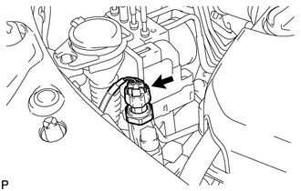
3. REMOVE AIR CONDITIONING PRESSURE SENSOR
|
(a) Disconnect the connector. |
|
.png)
(b) Remove the air conditioning pressure sensor.
 Air Conditioning Panel
Components
COMPONENTS
ILLUSTRATION
Installation
INSTALLATION
PROCEDURE
1. INSTALL AIR CONDITIONING CONTROL ASSEMBLY
(a) Connect the connector.
(b) Engage the 2 clips and 4 gui ...

Other materials about Toyota Venza:
Problem Symptoms Table
PROBLEM SYMPTOMS TABLE
HINT:
Use the table below to help determine the cause of problem symptoms.
If multiple suspected areas are listed, the potential causes of the symptoms
are listed in order of probability in the "Suspected Area" ...
Problem Symptoms Table
PROBLEM SYMPTOMS TABLE
Use the table below to help determine the cause of problem symptoms.
If multiple suspected areas are listed, the potential causes of the symptoms
are listed in order of probability in the "Suspected Area" column ...
System Diagram
SYSTEM DIAGRAM
Communication Table
Transmitting ECU
Receiving ECU
Signal
Communication Method
Air Conditioning Control Assembly
Air Conditioning Amplifier Assembly
Rear windo ...

0.1608