Toyota Venza: Erasing the entire HomeLink® memory (all three programs)
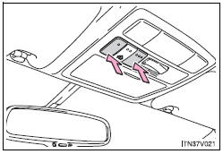
Press and hold the 2 outside buttons for 10 seconds (or 20 seconds depending on the model) until the indicator light flashes.
If you sell your vehicle, be sure to erase the programs stored in the HomeLink® memory.
- Before programming
• Install a new battery in the remote control transmitter.
• The battery side of the remote control transmitter must be pointed away from the HomeLink® button.
- Certification for the garage door opener
FCC ID: CB2300NHL3
FCC ID: CB2281AHL4
NOTE:
This device complies with Part 15 of the FCC Rules.
Operation is subject to the following two conditions: (1) this device may not cause harmful interference, and (2) this device must accept any interference received, including interference that may cause undesired operation.
FCC WARNING:
Changes or modifications not expressly approved by the party responsible for compliance could void the user’s authority to operate the equipment.
- For additional programming assistance with your HomeLink® Universal Transceiver
Visit on the web at www.homelink.com or call 1-800-355-3515.
CAUTION
- When programming a garage door or other remote control devices
The garage door or other devices may operate, so ensure people and objects are out of danger to prevent potential harm.
- Conforming to federal safety standards
Do not use the HomeLink® compatible transceiver with any garage door opener or device that lacks safety stop and reverse features as required by federal safety standards.
This includes any garage door that cannot detect an interfering object. A door or device without these features increases the risk of death or serious injury.
 Operating HomeLink®
Press the appropriate HomeLink® button. The HomeLink® indicator light should
come on.
The HomeLink® compatible transceiver in your vehicle continues to send a signal
for up to 20 seconds as lo ...
 Compass
The compass on the inside rear view mirror indicates the direction in which
the vehicle is heading.
- Operation
To turn the compass on or off, push and hold “AUTO” for longer than 3 se ...
Other materials about Toyota Venza:
Console boxes
► Front
Press the tab and slide to open.
► Rear
1. Pull up the lever to release the lock.
2. Slide the armrest fully rearward.
3. Lift the armrest to open.
- When using the rear console box lid as an armrest
If necessary, the con ...
Installation
INSTALLATION
CAUTION / NOTICE / HINT
HINT:
Use the same procedure for the RH side and LH side.
The procedure listed below is for the LH side.
PROCEDURE
1. INSTALL REAR AXLE CARRIER SUB-ASSEMBLY
(a) Temporarily install the rea ...
Open in Inside Luggage Compartment Electrical Key Oscillator Circuit (B27A7)
DESCRIPTION
The certification ECU (smart key ECU assembly) generates a request signal and
sends it to the indoor electrical key oscillator (for rear floor). To detect the
key inside the cabin, the indoor electrical key oscillator (for rear floor) creates ...

0.1719