Toyota Venza: Terminals Of Ecm
TERMINALS OF ECM
1. CHECK ECM
|
Terminal No. (Symbol) |
Wiring Color |
Terminal Description |
Condition |
Specified Condition |
|---|---|---|---|---|
|
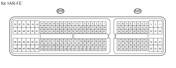
A49-7 (TC) - B58-104 (E1) |
V - BR |
Terminal TC of DLC3 |
Ignition switch ON |
11 to 14 V |
|
A49-7 (TC) - B58-104 (E1) |
V - BR |
Terminal TC of DLC3 |
Terminals TC and CG of DLC3 connected |
Below 1 V |
|
A49-29 (STP) - B58-104 (E1) |
G - BR |
Stop light switch signal |
Brake pedal depressed |
7.5 to 14 V |
|
A49-29 (STP) - B58-104 (E1) |
G - BR |
Stop light switch signal |
Brake pedal released |
Below 1 V |
|
A49-39 (ST1-) - B58-104 (E1) |
V - BR |
Stop light switch signal |
Ignition switch ON Brake pedal depressed |
Below 1 V |
|
A49-39 (ST1-) - B58-104 (E1) |
V - BR |
Stop light switch signal |
Ignition switch ON Brake pedal released |
7.5 to 14 V |
|
A49-40 (CCS) - B58-104 (E1) |
P - BR |
Cruise control main switch signal |
Ignition switch ON |
11 to 14 V |
|
A49-40 (CCS) - B58-104 (E1) |
P - BR |
Cruise control main switch signal |
CANCEL switch on |
6.6 to 10.1 V |
|
A49-40 (CCS) - B58-104 (E1) |
P - BR |
Cruise control main switch signal |
- SET switch on |
4.5 to 7.1 V |
|
A49-40 (CCS) - B58-104 (E1) |
P - BR |
Cruise control main switch signal |
+ RES switch on |
2.3 to 4.0 V |
|
A49-40 (CCS) - B58-104 (E1) |
P - BR |
Cruise control main switch signal |
MAIN switch on |
Below 1 V |
|
Terminal No. (Symbol) |
Wiring Color |
Terminal Description |
Condition |
Specified Condition |
|---|---|---|---|---|
|
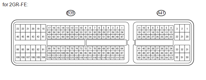
A41-16 (TC) - B39-81 (E1) |
V - W |
Terminal TC of DLC3 |
Ignition switch ON |
11 to 14 V |
|
A41-16 (TC) - B39-81 (E1) |
V - W |
Terminal TC of DLC3 |
Terminals TC and CG of DLC3 connected |
Below 1 V |
|
A41-36 (STP) - B39-81 (E1) |
G - W |
Stop light switch signal |
Brake pedal depressed |
7.5 to 14 V |
|
A41-36 (STP) - B39-81 (E1) |
G - W |
Stop light switch signal |
Brake pedal released |
Below 1 V |
|
A41-35 (ST1-) - B39-81 (E1) |
V - W |
Stop light switch signal |
Ignition switch ON Brake pedal depressed |
Below 1 V |
|
A41-35 (ST1-) - B39-81 (E1) |
V - W |
Stop light switch signal |
Ignition switch ON Brake pedal released |
7.5 to 14 V |
|
A41-45 (CCS) - B39-81 (E1) |
P - W |
Cruise control main switch signal |
Ignition switch ON |
11 to 14 V |
|
A41-45 (CCS) - B39-81 (E1) |
P - W |
Cruise control main switch signal |
CANCEL switch on |
6.6 to 10.1 V |
|
A41-45 (CCS) - B39-81 (E1) |
P - W |
Cruise control main switch signal |
- SET switch on |
4.5 to 7.1 V |
|
A41-45 (CCS) - B39-81 (E1) |
P - W |
Cruise control main switch signal |
+ RES switch on |
2.3 to 4.0 V |
|
A41-45 (CCS) - B39-81 (E1) |
P - W |
Cruise control main switch signal |
MAIN switch on |
Below 1 V |
 Diagnosis System
DIAGNOSIS SYSTEM
1. DESCRIPTION
The ECM controls the cruise control system of the vehicle. The data and DTCs
relating to the cruise control system can be read from the DLC3 of the vehicle.
If ei ...
 Dtc Check / Clear
DTC CHECK / CLEAR
1. CHECK DTC
(a) Connect the Techstream to the DLC3.
(b) Turn the ignition switch to ON.
(c) Turn the Techstream on.
(d) Enter the following menus: Powertrain / Cruise Control / ...
Other materials about Toyota Venza:
Portable Player cannot be Registered
CAUTION / NOTICE / HINT
HINT:
Some versions of "Bluetooth" compatible audio players may not function properly,
or the functions may be limited using the radio and display receiver assembly, even
if the portable audio player itself can play file ...
Electrical Key Oscillator(for Front Floor)
Components
COMPONENTS
ILLUSTRATION
Installation
INSTALLATION
PROCEDURE
1. INSTALL ELECTRICAL KEY OSCILLATOR
(a) Engage the clamp and install the electrical key oscillator.
NOTICE:
Be careful when installing the electrical key osci ...
Rear Power Window RH Auto Up / Down Function does not Operate with Rear Power
Window Switch RH
DESCRIPTION
If the manual up/down function can be performed but the auto up/down function
cannot, the fail-safe mode may be functioning.
If the power window initialization (See page
) has not been performed, the auto up/down function
will not operate.
...

0.1372