Toyota Venza: Components
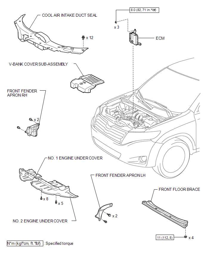
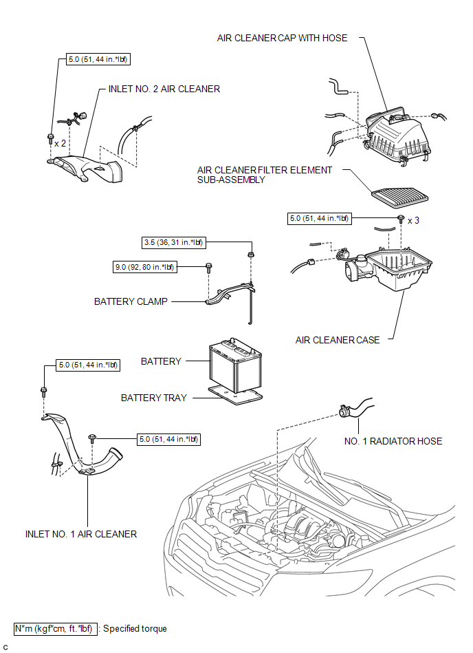
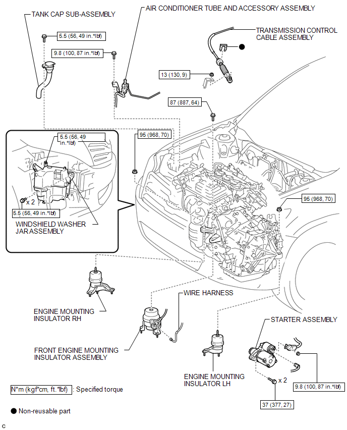
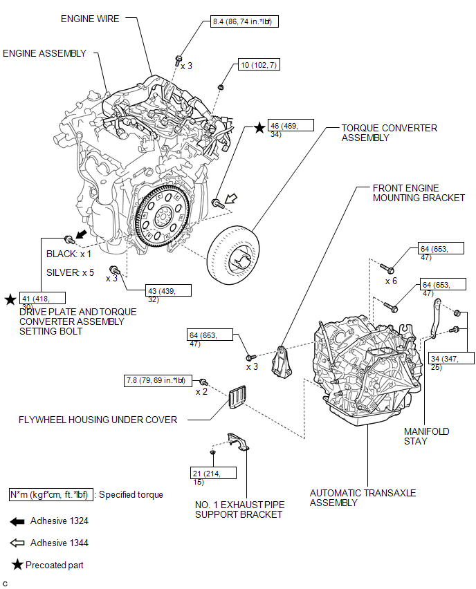
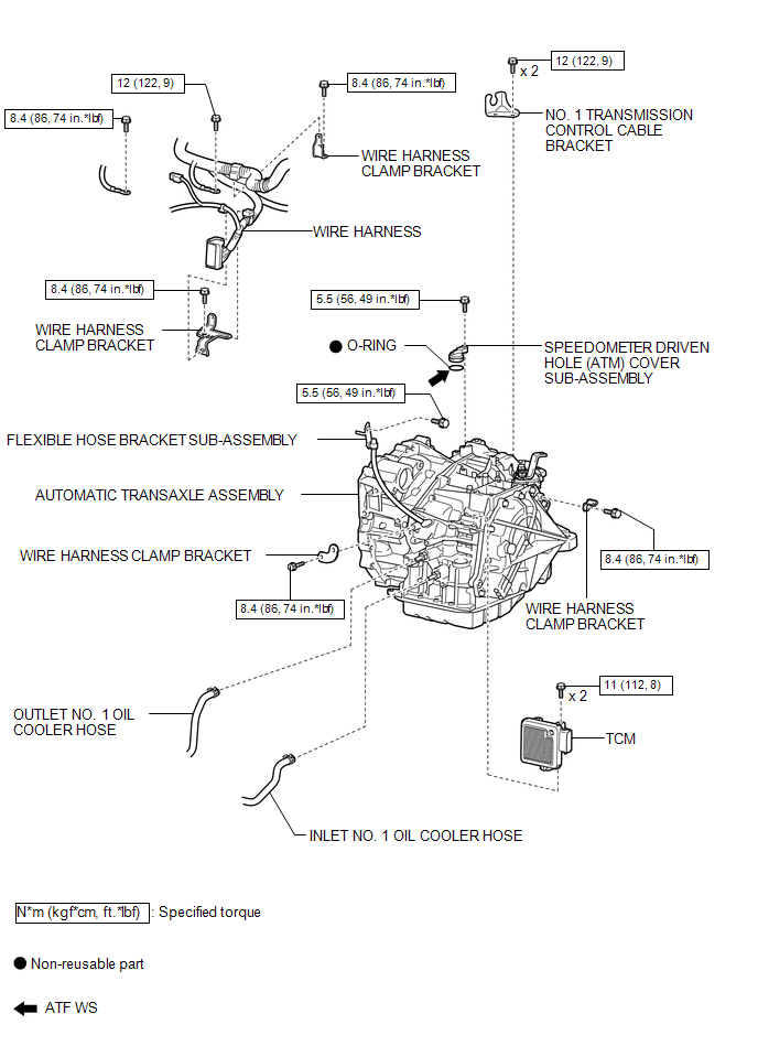
COMPONENTS
ILLUSTRATION
ILLUSTRATION
ILLUSTRATION
ILLUSTRATION
ILLUSTRATION

 Removal
REMOVAL
CAUTION / NOTICE / HINT
NOTICE:
If automatic transaxle assembly parts are replaced, refer to Parts Replacement
Compensation Table to determine if any additional operations are necessary ( ...
Other materials about Toyota Venza:
ACC Signal Circuit
DESCRIPTION
This circuit detects the ignition switch ACC or off condition, and sends it to
the main body ECU (driver side junction block assembly).
WIRING DIAGRAM
CAUTION / NOTICE / HINT
NOTICE:
Inspect the fuses for circuits related to this system ...
Control Module Performance (P0607)
MONITOR DESCRIPTION
The ECM continuously monitors its internal processors (CPUs) and heated oxygen
sensor transistors. This self-check ensures that the ECM is functioning properly.
DTC No.
DTC Detection Condition
Trouble Ar ...
Dtc Check / Clear
DTC CHECK / CLEAR
1. CHECK DTC
(a) Connect the Techstream to the DLC3.
(b) Turn the ignition switch to ON.
(c) Turn the Techstream on.
(d) Enter the following menus: Body Electrical / (desired system) / Trouble Codes.
(e) Check for DTCs.
2. CLEAR DTC
( ...

0.1305