Toyota Venza: Removal
REMOVAL
PROCEDURE
1. REMOVE ENGINE OIL LEVEL DIPSTICK GUIDE
|
(a) Remove the engine oil level dipstick. |
|
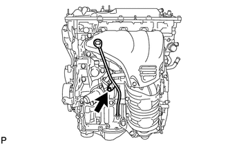
(b) Remove the bolt and engine oil level dipstick guide.
(c) Remove the O-ring from the engine oil level dipstick guide.
2. REMOVE NO. 1 EXHAUST MANIFOLD HEAT INSULATOR
.gif)
3. REMOVE MANIFOLD STAY
4. REMOVE NO. 2 MANIFOLD STAY
5. REMOVE EXHAUST MANIFOLD CONVERTER SUB-ASSEMBLY
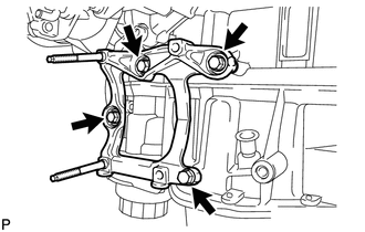
6. REMOVE NO. 1 COMPRESSOR MOUNTING BRACKET
|
(a) Remove the 4 bolts and bracket. |
|
7. REMOVE THROTTLE BODY ASSEMBLY
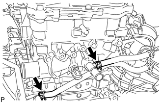
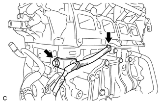
8. REMOVE WATER BY-PASS HOSE
|
(a) Remove the No. 1 and No. 2 water by-pass hoses. |
|
9. DISCONNECT NO. 2 VENTILATION HOSE
10. REMOVE INTAKE MANIFOLD
11. REMOVE SENSOR WIRE
|
(a) Disconnect the knock control sensor connector. |
|
(b) Remove the bolt and sensor wire.
12. REMOVE KNOCK CONTROL SENSOR
13. REMOVE ENGINE OIL PRESSURE SWITCH ASSEMBLY
14. REMOVE ENGINE COOLANT TEMPERATURE SENSOR
15. REMOVE FUEL DELIVERY PIPE SUB-ASSEMBLY
16. REMOVE IGNITION COIL ASSEMBLY
 Components
COMPONENTS
ILLUSTRATION
ILLUSTRATION
ILLUSTRATION
ILLUSTRATION
ILLUSTRATION
ILLUSTRATION
ILLUSTRATION
ILLUSTRATION
ILLUSTRATION
ILLUSTRATION
...
 Disassembly
DISASSEMBLY
PROCEDURE
1. REMOVE ENGINE COVER JOINT
(a) Remove the 3 joints.
2. REMOVE SPARK PLUG
3. REMOVE CAMSHAFT TIMING OIL CONTROL ...
Other materials about Toyota Venza:
Installation
INSTALLATION
PROCEDURE
1. INSPECT TORQUE CONVERTER ASSEMBLY
2. INSTALL TORQUE CONVERTER ASSEMBLY
(a) Engage the splines of the input shaft and turbine runner.
(b) Engage the splines o ...
Bleeding
BLEEDING
CAUTION / NOTICE / HINT
NOTICE:
Do not allow brake fluid to adhere to any painted surface such as the
vehicle body. If brake fluid leaks onto any painted surface, immediately
wash it off.
Before bleeding the brake system, confir ...
Fail-safe Chart
FAIL-SAFE CHART
If a problem occurs in the power steering system, the power steering assist will
be stopped or the amount of power assist will be decreased to protect the system.
Power Steering System
Malfunction
Fail-safe Operation
...

0.152