Toyota Venza: TC and CG Terminal Circuit
DESCRIPTION
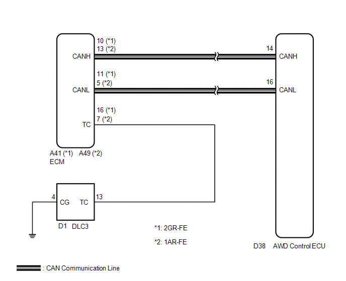
Connecting terminals TC and CG of the DLC3 causes the AWD control ECU to display 2-digit DTCs by flashing the AWD warning light.
HINT:
When each warning light remains blinking, a short to ground in the wiring of terminal TC of the DLC3 or an internal short to ground in each ECU is suspected.
WIRING DIAGRAM
CAUTION / NOTICE / HINT
HINT:
Check the condition of each related circuit connector before troubleshooting
(See page .gif) ).
).
PROCEDURE
|
1. |
CHECK CAN COMMUNICATION SYSTEM |
(a) Check if the CAN communication DTC is output (See page
).
|
Result |
Proceed to |
|---|---|
|
DTC is not output |
A |
|
DTC is output |
B |
| B | .gif) |
REPAIR CAN COMMUNICATION SYSTEM |
|
.gif)
|
2. |
CHECK WIRE HARNESS (TC OF DLC3 - TC OF ECM AND BODY GROUND) |
|
(a) Turn the ignition switch off. |
|
(b) Disconnect the ECM connector.
(c) Measure the resistance of the wire harness side connectors.
Standard Resistance:
|
Tester Connection (DLC3 - ECM) |
Condition |
Specified Condition |
|---|---|---|
|
D1-13 (TC) - A41-16 (TC) |
Always |
Below 1 Ω |
|
D1-13 (TC) - A49-7 (TC) |
Always |
Below 1 Ω |
|
D1-13 (TC) - Body Ground |
Always |
10 kΩ or higher |
|
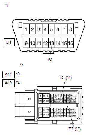
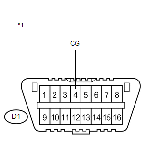
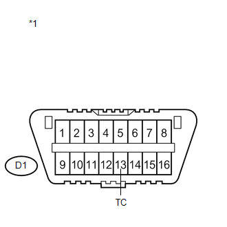
*1 |
DLC3 |
|
*2 |
Front view of wire harness connector (to ECM) |
|
*3 |
2GR-FE |
|
*4 |
1AR-FE |
| NG | |
REPAIR OR REPLACE HARNESS OR CONNECTOR |
|
|
3. |
CHECK WIRE HARNESS (CG OF DLC3 - BODY GROUND) |
|
(a) Measure the resistance of the DLC3. Standard Resistance:
|
|
| NG | |
REPAIR OR REPLACE HARNESS OR CONNECTOR |
|
|
4. |
CHECK WIRE HARNESS (TC OF DLC3 - BODY GROUND) |
|
(a) Measure the resistance of the DLC3. Standard Resistance:
|
|
| OK | |
REPLACE AWD CONTROL ECU |
| NG | |
REPAIR OR REPLACE HARNESS OR CONNECTOR |
 AWD Warning Light Remains ON
DESCRIPTION
The AWD control ECU is connected to the combination meter via the CAN communication
system.
If the AWD control ECU stores any DTCs which are related to the active torque
control 4WD ...

Other materials about Toyota Venza:
Problem Symptoms Table
PROBLEM SYMPTOMS TABLE
HINT:
Use the table below to help determine the cause of problem symptoms.
If multiple suspected areas are listed, the potential causes of the symptoms
are listed in order of probability in the "Suspected Area" ...
Camshaft Position Sensor
Components
COMPONENTS
ILLUSTRATION
Installation
INSTALLATION
PROCEDURE
1. INSTALL CAMSHAFT POSITION SENSOR (for Exhaust Side)
(a) Apply a light coat of engine oil to the O-ring of the camshaft position sensor.
NOTICE:
If reusing the camshaft pos ...
Precaution
PRECAUTION
NOTICE:
When disconnecting the cable from the negative (-) battery terminal, initialize
the following systems after the cable is reconnected.
System Name
See Procedure
Back Door Closer System
...

0.1483