Toyota Venza: TC and CG Terminal Circuit
DESCRIPTION
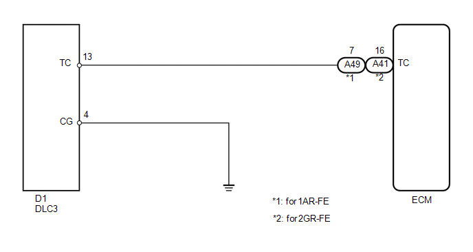
Connecting terminals TC and CG of the DLC3 causes the system to enter self-diagnostic mode. If a malfunction is present, the MIL will blink.
HINT:
When a particular warning light remains blinking, a ground short in the wiring of terminal TC of the DLC3 or an internal ground short in the relevant ECU is suspected.
WIRING DIAGRAM
PROCEDURE
|
1. |
CHECK HARNESS AND CONNECTOR (DLC3 - ECM) |
(a) Disconnect the ECM connector.
(b) Measure the resistance according to the value(s) in the table below.
Standard Resistance:
For 1AR-FE|
Tester Connection |
Condition |
Specified Condition |
|---|---|---|
|
D1-13 (TC) - A49-7 (TC) |
Always |
Below 1 Ω |
|
Tester Connection |
Condition |
Specified Condition |
|---|---|---|
|
D1-13 (TC) - A41-16 (TC) |
Always |
Below 1 Ω |
|
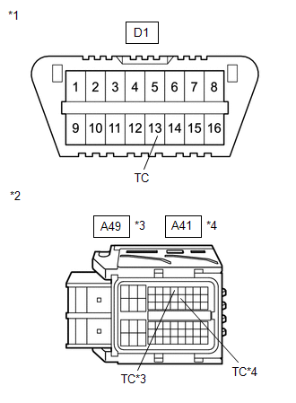
*1 |
DLC3 |
|
*2 |
Front view of wire harness connector (to ECM) |
|
*3 |
for 1AR-FE |
|
*4 |
for 2GR-FE |
(c) Reconnect the ECM connector.
| NG | .gif) |
REPAIR OR REPLACE HARNESS OR CONNECTOR (DLC3 - ECM) |
|
.gif)
|
2. |
CHECK HARNESS AND CONNECTOR (DLC3 - BODY GROUND) |
(a) Measure the resistance according to the value(s) in the table below.
Standard Resistance:
|
Tester Connection |
Condition |
Specified Condition |
|---|---|---|
|
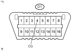
D1-4 (CG) - Body ground |
Always |
Below 1 Ω |
|
*1 |
DLC3 |
| NG | |
REPAIR OR REPLACE HARNESS OR CONNECTOR (DLC3 - BODY GROUND) |
|
|
3. |
CHECK HARNESS AND CONNECTOR (DLC3 - BODY GROUND) |
(a) Measure the resistance according to the value(s) in the table below.
Standard Resistance:
|
Tester Connection |
Condition |
Specified Condition |
|---|---|---|
|
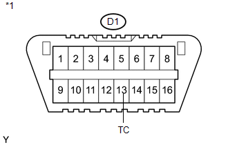
D1-13 (TC) - Body ground |
Always |
10 kΩ or higher |
|
*1 |
DLC3 |
| OK | |
PROCEED TO NEXT SUSPECTED AREA SHOWN IN PROBLEM SYMPTOMS TABLE |
| NG | |
REPAIR OR REPLACE HARNESS OR CONNECTOR OR EACH ECU |
 Cruise SET Indicator Light Circuit
DESCRIPTION
The ECM detects a cruise control switch signal and sends it to the combination
meter assembly through CAN. Then the SET indicator light comes on.
The SET indicator light ci ...

Other materials about Toyota Venza:
Removal
REMOVAL
PROCEDURE
1. PRECAUTION
(See page )
2. ALIGN FRONT WHEELS FACING STRAIGHT AHEAD
3. DISCONNECT CABLE FROM NEGATIVE BATTERY TERMINAL
CAUTION:
Wait at least 90 seconds after disconnecting the cable from the negative (-)
battery terminal to disab ...
Problem Symptoms Table
PROBLEM SYMPTOMS TABLE
HINT:
Use the table below to help determine the cause of problem symptoms. If multiple
suspected areas are listed, the potential causes of the symptoms are listed in order
of probability in the "Suspected Area" column of ...
Installation
INSTALLATION
CAUTION / NOTICE / HINT
HINT:
Use the same procedure for the RH side and LH side.
The procedure listed below is for the LH side.
PROCEDURE
1. INSTALL FRONT POWER WINDOW REGULATOR MOTOR ASSEMBLY
NOTICE:
The regulator arm mu ...

0.1596