Toyota Venza: Taking out the jack
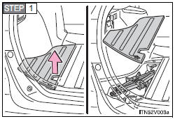
Remove the left side deck board.
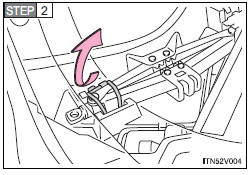
Unlock the tightening strap.
After storing the jack, make sure it is securely held by the tightening strap.
 If you have a flat tire
Remove the flat tire and replace it with the spare provided. - Before
jacking up the vehicle
• Stop the vehicle on a hard, flat surface.
• Set the parking brake.
• Shift the shift lever to ...
 Taking out the spare tire
Loosen the center fastener that secures the spare tire. ...
Other materials about Toyota Venza:
Front seats
► Power seat
1. Seat position fore/aft control switch
2. Seatback angle control switch
3. Seat cushion (front) angle control switch (driver’s side only)
4. Vertical height control switch (driver’s side only)
5. Lumbar support control switch
& ...
Security Indicator Light Circuit
DESCRIPTION
Even when the theft deterrent system is in the disarmed state, the security indicator
blinks due to a signal output from the immobiliser system. The security indicator
blinks continuously due to a continuous signal received from the immobilise ...
Installing the spare tire
Remove any dirt or foreign matter from the wheel contact surface.
If foreign matter is on the wheel contact surface, the wheel nuts may loosen
while the vehicle is in motion, and the tire may come off the vehicle.
Install the spare tire and loosely tig ...

0.1316