Toyota Venza: Front Brake Flexible Hose
Components
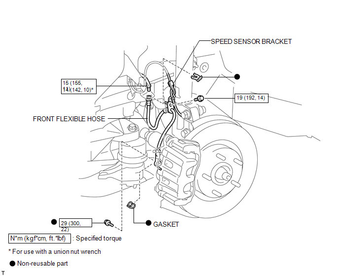
COMPONENTS
ILLUSTRATION
Installation
INSTALLATION
CAUTION / NOTICE / HINT
NOTICE:
- Because the left and right hoses are not interchangeable, verify the part number when installing the flexible hoses.
- If the hoses are to be reused, connect them after checking the identification marks placed when each hose was disconnected.
PROCEDURE
1. INSTALL FRONT FLEXIBLE HOSE
|
(a) Connect the front flexible hose to the disc brake cylinder assembly with a new union bolt and a new gasket. Torque: 29 N·m {300 kgf·cm, 22 ft·lbf} HINT: Install the front flexible hose lock securely into the lock hole in the front disc brake cylinder assembly. |
|
.png)
|
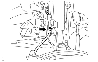
(b) Install the front flexible hose with a new clip. NOTICE: Install the clip as far as it will go. |
|

|
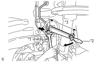
(c) Using a union nut wrench, connect the brake line to the front flexible hose while holding the front flexible hose with a wrench. Text in Illustration
Torque: Specified Tightening Torque : 15 N·m {155 kgf·cm, 11 ft·lbf} NOTICE:
HINT:
|
|
|
(d) Install the front flexible hose together with the speed sensor bracket to the absorber bracket with the bolt. Torque: 19 N·m {192 kgf·cm, 14 ft·lbf} NOTICE: First install the speed sensor harness bracket, and then install the flexible hose bracket. |
|
2. FILL RESERVOIR WITH BRAKE FLUID
.gif)
3. BLEED BRAKE LINE
4. INSPECT FOR BRAKE FLUID LEAK
5. INSPECT FLUID LEVEL IN RESERVOIR
6. INSTALL FRONT WHEEL
Torque:
103 N·m {1050 kgf·cm, 76 ft·lbf}
Removal
REMOVAL
CAUTION / NOTICE / HINT
NOTICE:
If both the left and right side hoses are removed at the same time, be sure to place identification marks indicating the position on each side.
HINT:
- Use the same procedure for the LH side and RH side.
- The following procedure listed is for the LH side.
PROCEDURE
1. REMOVE FRONT WHEEL
2. DRAIN BRAKE FLUID
NOTICE:
If brake fluid leaks onto any painted surface, immediately wash it off.
3. REMOVE FRONT FLEXIBLE HOSE
|
(a) Remove the union bolt and gasket, and separate the front flexible hose. |
|
.png)
|
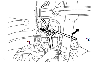
(b) Using a union nut wrench, disconnect the brake line from the front flexible hose while holding the front flexible hose with a wrench. Text in Illustration
NOTICE:
|
|
|
(c) Remove the clip. |
|
.png)
|
(d) Remove the bolt and front flexible hose from the absorber bracket. |
|
.png)
 Installation
INSTALLATION
PROCEDURE
1. TEMPORARILY TIGHTEN FRONT DISC BRAKE BLEEDER PLUG
(a) Temporarily tighten the front disc brake bleeder plug.
HINT:
Fully tighten the front disc brake bleeder plug after ...
 Brake (rear)
...
Other materials about Toyota Venza:
TC and CG Terminal Circuit
DESCRIPTION
Connecting terminals TC and CG of the DLC3 causes the system to enter self-diagnostic
mode. If a malfunction is present, the MIL will blink.
HINT:
When a particular warning light remains blinking, a ground short in the wiring
of terminal TC ...
Back-up Power Source Circuit
DESCRIPTION
The back-up power source circuit for the A/C amplifier is shown below. Power
is supplied even when the ignition switch is turned off. The power is used for diagnostic
trouble code memory, etc.
WIRING DIAGRAM
CAUTION / NOTICE / HINT
NOTICE ...
System Diagram
SYSTEM DIAGRAM
1. AUTOMATIC LIGHT CONTROL SYSTEM
2. LIGHT AUTO TURN-OFF SYSTEM
Communication Table
Transmitter
Receiver
Line
Data Name
Certification ECU (Smart Key ECU Assembly)
Mai ...

0.135