Toyota Venza: System Diagram
SYSTEM DIAGRAM
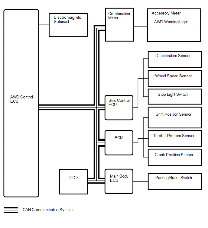 Communication Table
|
Transmitting ECU |
Receiving ECU |
Signal |
Communication Method |
|---|---|---|---|
|
Skid control ECU |
AWD control ECU |
|
CAN communication system |
|
ECM |
AWD control ECU |
|
CAN communication system |
|
Main body ECU |
AWD control ECU |
Parking brake switch signal |
CAN communication system |
|
AWD control ECU |
Combination meter |
AWD warning light signal |
CAN communication system |
 System Description
SYSTEM DESCRIPTION
1. FUNCTION OF MAIN COMPONENTS
Component
Function
Accessory Meter Assembly
AWD Warning Light
Illuminates to ...
 How To Proceed With Troubleshooting
CAUTION / NOTICE / HINT
HINT:
Use the following procedure listed to troubleshoot the Active Torque
Control 4WD system.
*: Use the Techstream.
PROCEDURE
1.
...
Other materials about Toyota Venza:
ACC Signal Circuit
DESCRIPTION
This circuit detects the ignition switch ACC or off condition, and sends it to
the main body ECU (driver side junction block assembly).
WIRING DIAGRAM
CAUTION / NOTICE / HINT
NOTICE:
Inspect the fuses for circuits related to this system ...
Terminals Of Ecu
TERMINALS OF ECU
1. CHECK TIRE PRESSURE WARNING ECU
HINT:
Inspect the connectors from the back side while the connectors are connected.
(a) Disconnect the L14 tire pressure warning antenna and receiver connector.
(b) Measure the voltage according to the ...
System Description
SYSTEM DESCRIPTION
1. TOUCH SWITCH OUTLINE
(a) Touch switches are touch-sensitive (interactive) switches operated by touching
the screen. When a switch is pressed, the outer film bends in to contact the inner
glass at the pressed position. By doing this, ...

0.1278