Toyota Venza: Disassembly
DISASSEMBLY
PROCEDURE
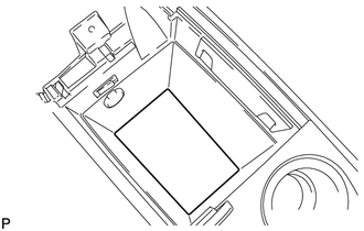
1. REMOVE NO. 1 CONSOLE BOX CARPET
|
(a) Remove the No. 1 console box carpet. |
|
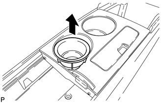
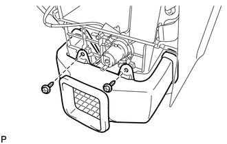
2. REMOVE INSTRUMENT PANEL CUP HOLDER DAMPER
|
(a) Pull the instrument panel cup holder damper in the direction indicated by the arrow to remove the instrument panel cup holder damper. |
|
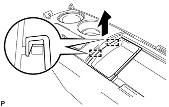
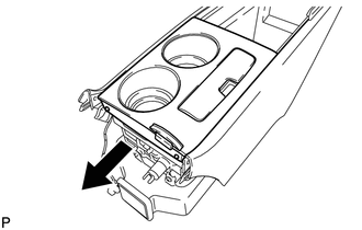
3. REMOVE CONSOLE BOX POCKET
|
(a) Pull the console box pocket in the direction indicated by the arrow to disengage the 2 guides and remove the console box pocket. |
|
4. REMOVE FRONT CONSOLE BOX COVER
|
(a) Disengage the clamp. |
|
(b) Remove the 3 screws.
(c) Disengage the 2 claws and remove the front console box cover.
5. REMOVE STEREO JACK ADAPTER ASSEMBLY
.gif)
6. REMOVE REAR CONSOLE UPPER PANEL SUB-ASSEMBLY
|
(a) Slide the rear console upper panel sub-assembly in the direction indicated by the arrow and remove the rear console upper panel sub-assembly. |
|
7. REMOVE NO. 2 CONSOLE BOX DUCT
|
(a) Remove the 2 screws and the No. 2 console box duct. |
|
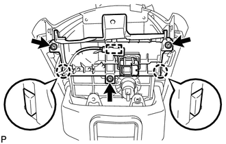
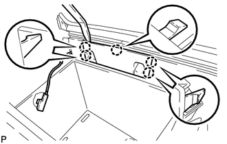
8. REMOVE CONSOLE MOUNTING RETAINER ASSEMBLY
|
(a) Using a moulding remover, disengage the 5 claws and remove the console mounting retainer assembly. |
|
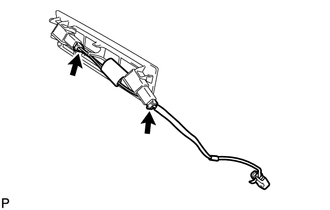
9. REMOVE CONSOLE BOX WIRE
|
(a) Disconnect the connectors to remove the console box wire. |
|
10. REMOVE CONSOLE BOX ILLUMINATION LIGHT ASSEMBLY
11. REMOVE CENTER POWER POINT SOCKET ASSEMBLY
12. REMOVE CENTER POWER OUTLET SOCKET COVER
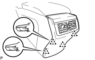
13. REMOVE REAR CONSOLE END PANEL SUB-ASSEMBLY
|
(a) Disengage the 4 clips and remove the rear console end panel sub-assembly. |
|
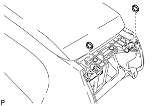
14. REMOVE REAR CONSOLE ARMREST ASSEMBLY
|
(a) Using a screwdriver, remove the 2 E-rings. NOTICE: Be careful not to allow the E-rings to pop out when removing them. |
|
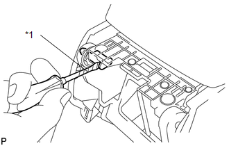
|
(b) Using a screwdriver, pull out the box door hinge shafts. Text in Illustration
HINT:
|
|
(c) Remove the rear console armrest assembly.
 Components
COMPONENTS
ILLUSTRATION
ILLUSTRATION
...
 Removal
REMOVAL
PROCEDURE
1. REMOVE UPPER CONSOLE PANEL SUB-ASSEMBLY (w/o Seat Heater System)
2. REMOVE UPPER CONSOLE PANEL SUB-ASSEMBLY (w/ Seat Heater System)
3. REMOVE NO. 2 CONSOLE BOX CARPET
...
Other materials about Toyota Venza:
Installation
INSTALLATION
CAUTION / NOTICE / HINT
HINT:
Use the same procedure for the RH side and LH side.
The procedure listed below is for the LH side.
PROCEDURE
1. INSTALL REAR STRUT ROD ASSEMBLY (for 2WD)
(a) Temporarily install the ...
Inspection
INSPECTION
PROCEDURE
1. INSPECT FRONT SEATBACK HEATER LH
(a) Apply battery voltage and check the seatback heater.
OK:
Measurement Connection
Condition
Specified Condition
...
Dtc Check / Clear
DTC CHECK / CLEAR
1. CHECK DTC
(a) Connect the Techstream to the DLC3.
(b) Turn the ignition switch to ON.
(c) Turn the Techstream on.
(d) Enter the following menus: Body Electrical / Navigation System / Trouble
Codes.
(e) Check for DTCs (See page ).
...

0.144