
Toyota Venza: System Description
SYSTEM DESCRIPTION
1. FUNCTION OF MAIN COMPONENTS
|
Component |
Function |
|
|---|---|---|
|
Accessory Meter Assembly |
AWD Warning Light |
|
|
Speed Sensors (4) |
Detects the wheel speed of each wheel. |
|
|
Crankshaft Position Sensor |
Detects the engine speed and outputs it to the ECM. |
|
|
Throttle Position Sensor |
Detects the throttle valve position and outputs it to the ECM. |
|
|
Park/Neutral Position Switch Assembly |
Detects the shift position of the transaxle and outputs it to the ECM. |
|
|
Stop Light Switch Assembly |
Detects when the brake pedal is depressed. |
|
|
Parking Brake Switch Assembly |
Detects when the parking brake is applied. |
|
|
Deceleration Sensor |
Detects the vehicle's longitudinal acceleration and deceleration |
|
|
Transfer |
Drive force input into the differential is redirected 90 degrees and output to the propeller shaft by the transfer. |
|
|
Rear Differential |
Electromagnetic Control Coupling - Electromagnetic Solenoid |
Distributes drive torque in accordance with the amperage applied by the AWD control ECU. |
|
AWD Control ECU |
|
|
|
ECM |
Outputs signals such as the shift position signal, throttle position signal, and crankshaft position signal to the AWD control ECU. |
|
|
Skid Control ECU |
Outputs signals such as the vehicle speed signal and deceleration signal to the AWD control ECU. |
|
|
Main Body ECU (Instrument Panel Junction Block) |
Outputs signals such as the parking brake signal to the AWD control ECU. |
|
2. OPERATION
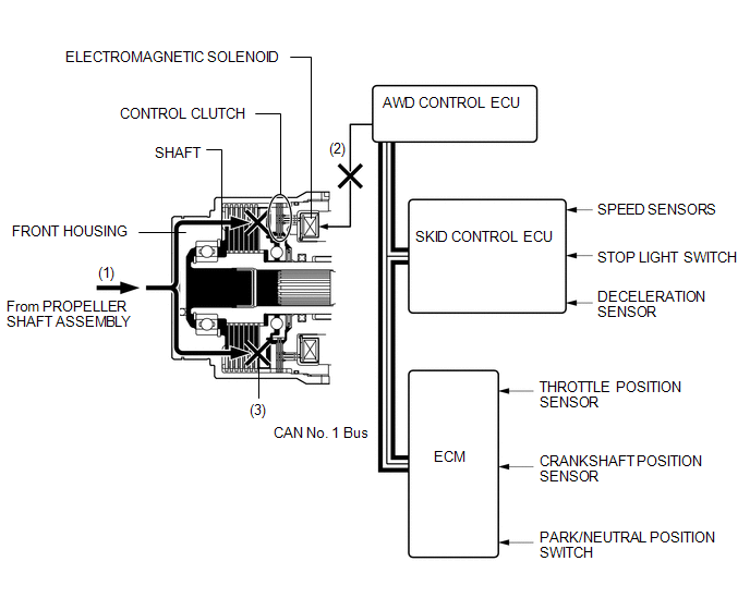
(a) 2WD Mode
(1) The drive force is transmitted from the propeller shaft to the front housing.
(2) The AWD control ECU judges whether it is necessary to send drive torque to the rear wheels based on input from various sensors. When it is not necessary to send drive torque to the rear wheels, the electromagnetic solenoid is not operated.
(3) The drive force of the front housing is not transmitted to the shaft because the control clutch is not engaged.
(4) Accordingly, drive force from the propeller shaft is not transmitted to the rear wheels.
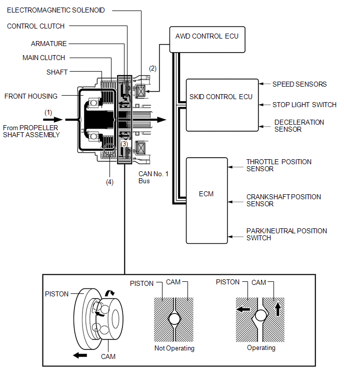
(b) AWD Mode
(1) The drive force is transmitted from the propeller shaft to the front housing.
(2) The AWD control ECU judges whether it is necessary to send drive torque to the rear wheels based on input from various sensors. When it is necessary to send drive torque to the rear wheels, the electromagnetic solenoid is operated.
(3) It attracts the armature to the control clutch side. This causes the control clutch to engage and the cam to rotate.
(4) The rotational movement of the cam causes the piston to push on the main clutch, causing the main clutch to engage.
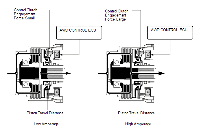
(5) The amount of drive force that is transmitted to the rear wheels is controlled steplessly by controlling the amperage that is applied to the electromagnetic solenoid.
(6) Accordingly, drive force from the propeller shaft is transmitted to the rear wheels.
 Parts Location
PARTS LOCATION
ILLUSTRATION
ILLUSTRATION
...
 System Diagram
SYSTEM DIAGRAM
Communication Table
Transmitting ECU
Receiving ECU
Signal
Communication Method
Skid control ECU
AWD control EC ...
Other materials about Toyota Venza:
Removal
REMOVAL
PROCEDURE
1. REMOVE REAR SEAT HEADREST ASSEMBLY
2. REMOVE REAR SEAT INNER TRACK BRACKET COVER
3. REMOVE REAR SEAT OUTER TRACK BRACKET COVER
4. DISCONNECT REAR SEAT NO. 2 RECLINING CONTROL CABLE SUB-ASSEMBLY
5. REMOVE REAR SEAT ASSEMBL ...
Problem Symptoms Table
PROBLEM SYMPTOMS TABLE
If there are no DTCs output and the problem still occurs, check the circuits
for each problem symptom in the order given in the following table and proceed to
the relevant troubleshooting page.
NOTICE:
When replacing the brake act ...
Removal
REMOVAL
CAUTION / NOTICE / HINT
CAUTION:
Wear protective gloves when removing the exhaust pipe.
The exhaust pipe is extremely hot immediately after the engine has stopped.
Confirm that the exhaust pipe has cooled down ...

0.1264