Toyota Venza: System Diagram
SYSTEM DIAGRAM
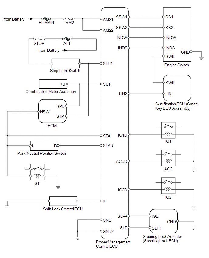
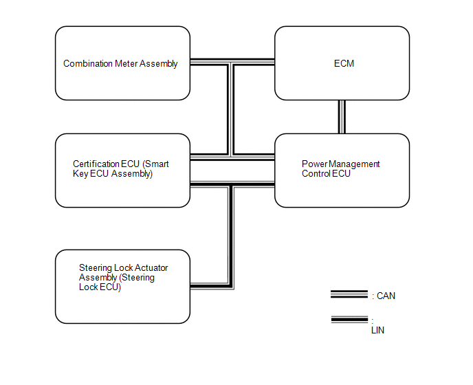 Communication Table
|
Transmitting ECU (Transmitter) |
Receiving ECU (Receiver) |
Signal |
Communication Method |
|---|---|---|---|
|
Combination meter |
Power management control ECU |
Vehicle speed signal |
CAN communication line/Local communication |
|
ECM |
Power management control ECU |
Stop light switch signal |
CAN communication line/Local communication |
|
ECM |
Power management control ECU |
Engine speed signal |
CAN/Local communication |
|
ECM |
Power management control ECU |
Shift position P signal |
CAN/Local communication |
|
Power management control ECU |
Combination meter |
Message request signal for push start |
CAN |
|
Power management control ECU |
Certification ECU (smart key ECU assembly) |
Shift position P signal |
LIN |
|
Power management control ECU |
Certification ECU (smart key ECU assembly) |
ID code certification result request signal |
LIN |
|
Power management control ECU |
Certification ECU (smart key ECU assembly) |
Power supply ON operation condition signal |
LIN |
|
Power management control ECU |
Certification ECU (smart key ECU assembly) |
Engine start operation condition signal |
LIN |
|
Power management control ECU |
Certification ECU (smart key ECU assembly) |
ACC relay drive condition signal |
LIN |
|
Steering lock actuator assembly (steering lock ECU) |
Certification ECU (smart key ECU assembly) |
Lock-side sensor condition signal |
LIN |
|
Steering lock actuator assembly (steering lock ECU) |
Certification ECU (smart key ECU assembly) |
Unlock-side sensor condition signal |
LIN |
|
Steering lock actuator assembly (steering lock ECU) |
Certification ECU (smart key ECU assembly) |
Sensor malfunction signal |
LIN |
|
Steering lock actuator assembly (steering lock ECU) |
Certification ECU (smart key ECU assembly) |
Lock lever engagement malfunction signal |
LIN |
|
Steering lock actuator assembly (steering lock ECU) |
Certification ECU (smart key ECU assembly) |
Abnormal push-signal |
LIN |
|
Steering lock actuator assembly (steering lock ECU) |
Certification ECU (smart key ECU assembly) |
Engine start permission signal |
LIN |
|
Steering lock actuator assembly (steering lock ECU) |
Certification ECU (smart key ECU assembly) |
L code certification condition signal |
LIN |
|
Certification ECU (smart key ECU assembly) |
Steering lock actuator assembly (steering lock ECU) |
Steering unlock request signal |
LIN |
|
Certification ECU (smart key ECU assembly) |
Steering lock actuator assembly (steering lock ECU) |
Steering lock request signal |
LIN |
|
Steering lock actuator assembly (steering lock ECU) |
Power management control ECU |
Unlock position signal |
LIN |
|
Power management control ECU |
Steering lock actuator assembly (steering lock ECU) |
Steering lock relay power supply condition signal |
LIN |
|
Power management control ECU |
Steering lock actuator assembly (steering lock ECU) |
IG relay drive condition signal |
LIN |
 Parts Location
PARTS LOCATION
ILLUSTRATION
ILLUSTRATION
...
 System Description
SYSTEM DESCRIPTION
1. PUSH-BUTTON START DESCRIPTION
(a) The push-button start uses a push-type engine switch, which the driver can
operate by merely carrying the electrical key. This system consis ...
Other materials about Toyota Venza:
Problem Symptoms Table
PROBLEM SYMPTOMS TABLE
HINT:
Use the table below to help determine the cause of problem symptoms.
If multiple suspected areas are listed, the potential causes of the symptoms
are listed in order of probability in the "Suspected Area" ...
How To Proceed With Troubleshooting
CAUTION / NOTICE / HINT
HINT:
Use the following procedure to troubleshoot the key reminder warning
system.
*: Use the Techstream.
PROCEDURE
1.
VEHICLE BROUGHT TO WORKSHOP
NEXT
...
Door Mirror Foot Light
Components
COMPONENTS
ILLUSTRATION
Removal
REMOVAL
CAUTION / NOTICE / HINT
HINT:
Use the same procedure for both the RH and LH sides.
The procedure described below is for the LH side.
PROCEDURE
1. REMOVE OUTER MIRROR
2. REM ...

0.1674