Toyota Venza: Parts Location
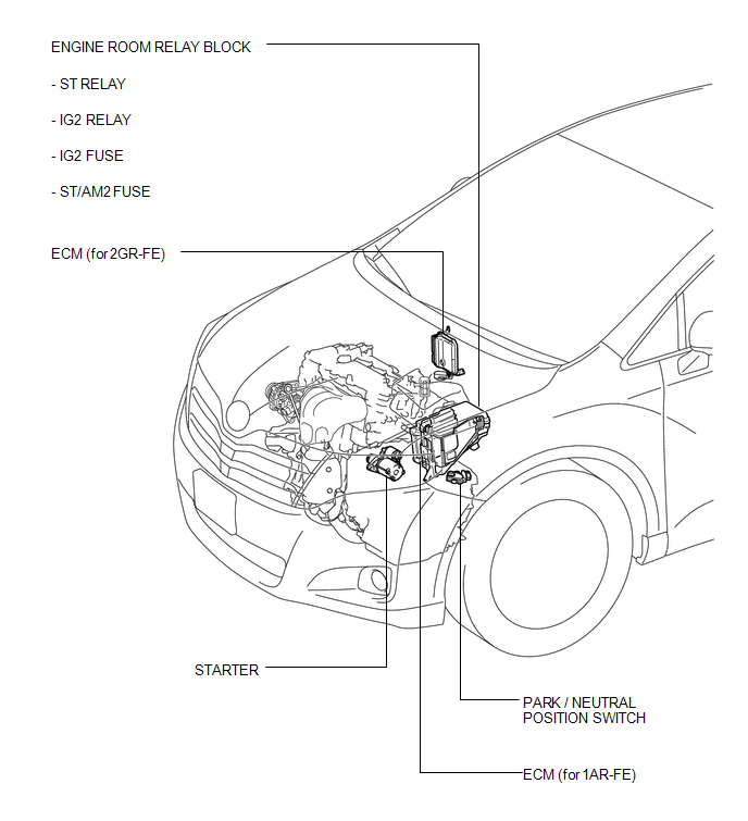
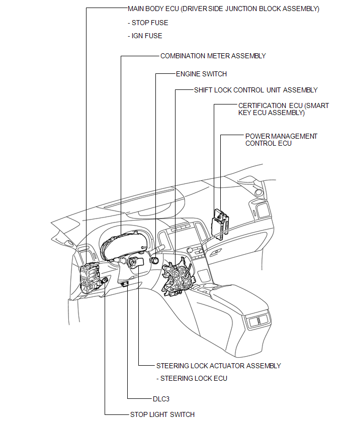
PARTS LOCATION
ILLUSTRATION
ILLUSTRATION
 Precaution
PRECAUTION
1. WHEN DISCONNECTING CABLE FROM NEGATIVE BATTERY TERMINAL
NOTICE:
When disconnecting the cable from the negative (-) battery terminal, initialize
the following systems after the cable ...
 System Diagram
SYSTEM DIAGRAM
Communication Table
Transmitting ECU
(Transmitter)
Receiving ECU
(Receiver)
Signal
Communication Method
Combinati ...
Other materials about Toyota Venza:
Reassembly
REASSEMBLY
CAUTION / NOTICE / HINT
HINT:
Perform "Inspection After Repair" after replacing the cylinder head sub-assembly
(See page ).
PROCEDURE
1. INSTALL SPARK PLUG TUBE
HINT:
When using a new cylinder head, the spark plug tubes must be r ...
Disassembly
DISASSEMBLY
PROCEDURE
1. REMOVE FUEL SENDER GAUGE
2. SEPARATE FUEL SUCTION PLATE SUB-ASSEMBLY
(a) Disconnect the fuel pump connector from the fuel suction plate.
NOTICE:
Do not damage the wire harness.
...
Disassembly
DISASSEMBLY
PROCEDURE
1. REMOVE STEERING RACK BOOT CLIP (for LH Side)
(a) Using pliers, remove the steering rack boot clip.
2. REMOVE STEERING RACK BOOT CLIP (for RH Side)
HINT:
Perform the same procedure as for the LH side.
3. REMOVE NO. 2 STEERING RAC ...

0.1521