Toyota Venza: System Diagram
SYSTEM DIAGRAM
 System Description
SYSTEM DESCRIPTION
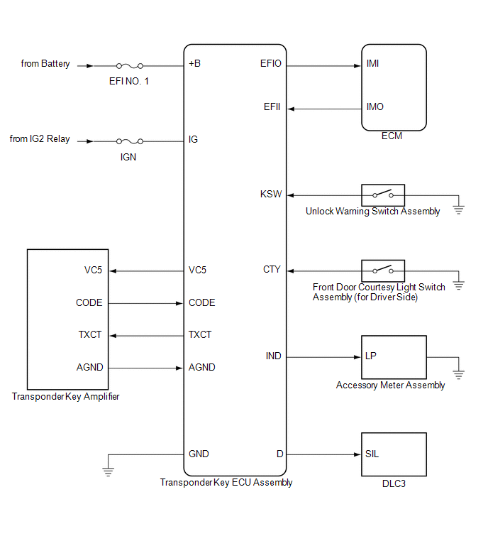
1. ENGINE IMMOBILISER SYSTEM DESCRIPTION
The engine immobiliser system is designed to prevent the vehicle from being stolen.
This system uses the transponder key ECU assembly th ...
 How To Proceed With Troubleshooting
CAUTION / NOTICE / HINT
HINT:
Use the following procedure to troubleshoot the engine immobiliser system.
*: Use the Techstream.
PROCEDURE
1.
VEHICLE BROUGHT TO WORKSHOP
...
Other materials about Toyota Venza:
Front Passenger Side Power Window does not Operate with Front Passenger Side
Power Window Switch
DESCRIPTION
When the engine is running or the ignition switch is ON, the power window regulator
motor assembly (for front passenger side) is operated by the power window regulator
switch assembly (for front passenger side). The power window regulator moto ...
Removal
REMOVAL
PROCEDURE
1. DISCONNECT CABLE FROM NEGATIVE BATTERY TERMINAL
NOTICE:
When disconnecting the cable, some systems need to be initialized after the cable
is reconnected (See page ).
2. REMOVE NO. 1 ENGINE COVER SUB-ASSEMBLY
3. REMOVE COOL AIR ...
Dtc Check / Clear
DTC CHECK / CLEAR
1. DTC CHECK (USING SST CHECK WIRE)
(a) Check the DTCs (Current trouble codes).
(1) Turn the ignition switch to ON, and wait for approximately 60 seconds.
(2) Using SST, connect terminals TC and CG of the DLC3.
SST: 09843-18040
NOTICE ...

0.1324