Toyota Venza: System Description
SYSTEM DESCRIPTION
1. ENGINE IMMOBILISER SYSTEM DESCRIPTION
The engine immobiliser system is designed to prevent the vehicle from being stolen. This system uses the transponder key ECU assembly that stores the key codes of authorized ignition keys. If an attempt is made to start the engine using an unauthorized key, the ECU sends a signal to the ECM to prohibit fuel delivery and ignition, effectively disabling the engine.
2. FUNCTION OF MAIN COMPONENTS
|
Component |
Outline |
|---|---|
|
Transponder key ECU assembly |
When a key is inserted into the ignition key cylinder, the antenna coil receives the key code. Then the amplifier amplifies the ID code and outputs it to the transponder key ECU assembly. |
|
Transponder key amplifier |
When a key is inserted in the ignition key cylinder, the key coil receives the key code. Then the amplifier amplifies the ID code and outputs it to the transponder key ECU assembly. |
|
ECM |
The ECM receives ID verification results from the transponder key ECU assembly. The ECM also verifies the ECUs. Then judgment of whether to immobilise the engine is made. |
|
Unlock warning switch assembly |
The unlock warning switch assembly detects if the key is in the ignition key cylinder and outputs the result to the transponder key ECU assembly. |
|
Front door courtesy light switch assembly (for driver side) |
The front door courtesy light switch assembly (for driver side) is located on the driver door. This detects door status (open or closed) and outputs data to the transponder key ECU assembly. This turns on when the driver door is open and turns off when the door is closed. |
|
Accessory meter assembly (security indicator light) |
Depending on the operation of the transponder key ECU assembly, the security indicator light comes on or starts blinking. |
3. SYSTEM FUNCTION
(a) When the transponder key ECU assembly detects that the key unlock warning switch is on, the ECU provides current to the transponder key coil and produces a radio wave. A transponder chip in the key grip receives the radio wave. Upon receiving the radio wave, the transponder chip outputs a key ID code signal. The transponder key coil receives this signal, which is amplified by the transponder key amplifier, and the signal is transmitted to the ECU.
The ECU matches the key ID code with the vehicle ID code, which was previously registered in the ECU, and communicates the results to the ECM.
After the identification results show that the key ID code matches the vehicle ID code and the ECU has confirmed their match: 1) the immobiliser system does not immobilise the engine and the engine starting controls (fuel injection control and ignition control) enter standby mode; and 2) the ECU transmits a security indicator signal that communicates "indicator off" to the accessory meter assembly. Then, the accessory meter assembly turns off the security indicator light.
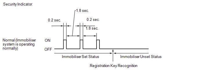
(b) The security indicator blinking pattern is as shown below (when changing from the immobiliser set status to the unset status):
 Parts Location
PARTS LOCATION
ILLUSTRATION
ILLUSTRATION
...
 System Diagram
SYSTEM DIAGRAM
...
Other materials about Toyota Venza:
Abnormal Temperature Inside ID1 Tire (C2165/65-C2168/68)
DESCRIPTION
Each tire pressure warning valve and transmitter measures the tire internal temperature
as well as tire pressure, and transmits the information to the tire pressure warning
ECU along with the transmitter ID. If the measured temperature is out ...
Steering Pad Switch Circuit
DESCRIPTION
This circuit sends an operation signal from the steering pad switch assembly
to the navigation receiver assembly.
If there is an open in the circuit, the audio system cannot be operated using
the steering pad switch assembly.
If there is a s ...
Operation Check
OPERATION CHECK
1. MALFUNCTION BUZZER
(a) Open circuit or frozen
(1) If an open circuit is detected between the ultrasonic sensors and the clearance
warning ECU assembly, if a sensor malfunction is detected or if a sensor is covered
with foreign matter, ...

0.1223