Toyota Venza: System Diagram
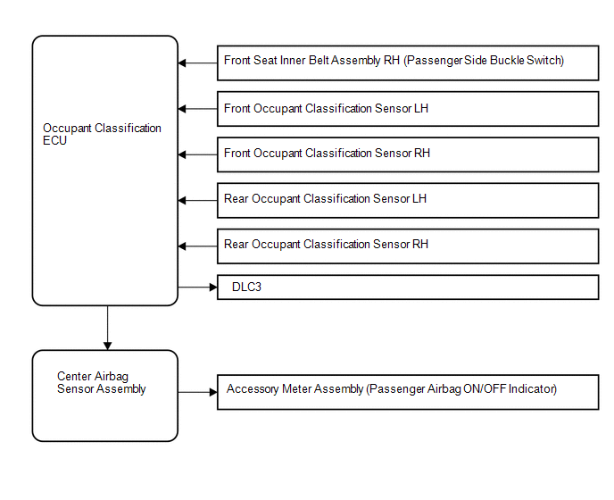
SYSTEM DIAGRAM
 Parts Location
PARTS LOCATION
ILLUSTRATION
...
 How To Proceed With Troubleshooting
CAUTION / NOTICE / HINT
HINT:
*: Use the Techstream
PROCEDURE
1.
VEHICLE BROUGHT TO WORKSHOP
NEXT
...
Other materials about Toyota Venza:
Adjustment
ADJUSTMENT
PROCEDURE
1. PRECAUTIONS AND WORK DESCRIPTION
(a) The U660E automatic transaxle does not have an oil filler tube and oil level
gauge. When adding fluid, add fluid through the refill hole on the transaxle case.
The fluid level can be adjusted ...
Illumination for Panel Switch does not Come on with Tail Switch ON
PROCEDURE
1.
CHECK VEHICLE SIGNAL (OPERATION CHECK)
(a) Enter the "Vehicle Signal Check Mode" screen. Refer to Check Vehicle Signal
in Operation Check (See page ).
(b) Check that the display changes between ON ...
Front Sensor Communication Malfunction (C1AEC)
DESCRIPTION
This DTC is stored when there is an open or short circuit in the communication
line between the front sensors and the ECU, or when there is a malfunction in a
front sensor.
DTC No.
DTC Detection Condition
Trou ...

0.122