
Toyota Venza: Key battery
Replace the battery with a new one if it is discharged.
- You will need the following items:
• Flathead screwdriver (To prevent damage to the key, cover the tip of the screwdriver
with rag.)
• Small Phillips-head screwdriver
• Lithium battery
Vehicles with smart key system: CR1632 Vehicles without smart key system: CR2025
- Replacing the battery (vehicles with smart key system)
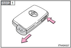
Take out the mechanical key.
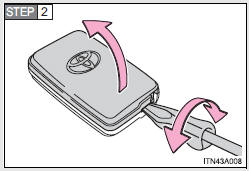
Remove the cover.
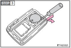
Remove the depleted battery.
Insert a new battery with the “+” terminal facing up.
- Replacing the battery (vehicles without smart key system)
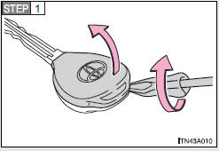
Remove the cover.
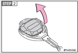
Remove the module.
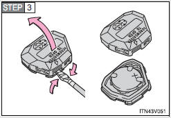
Open the case cover using a flathead screwdriver protected with tape etc. and remove the depleted battery.
Insert a new battery with the “+” terminal facing up.
- If the electronic key battery is discharged
The following symptoms may occur.
• The smart key system and wireless remote control will not function properly.
• The operational range is reduced.
- Use a CR1632 (vehicles with smart key system), or CR2025 (vehicles without smart key system) lithium battery
• Batteries can be purchased at your Toyota dealer, jewelers, or camera stores.
• Replace only with the same or equivalent type recommended by a Toyota dealer.
• Dispose of used batteries according to the local laws.
CAUTION
- Removed battery and other parts
These parts are small and if swallowed by a child they can cause choking.
Keep away from children. Failure to do so could result in death or serious injury.
NOTICE
- For normal operation after replacing the battery
Observe the following precautions to prevent accidents.
• Always work with dry hands.
Moisture may cause the battery to rust.
• Do not touch or move any other components inside the electronic key.
• Do not bend the battery terminals.
 Air conditioning filter
The air conditioning filter must be changed regularly to maintain air conditioning
efficiency.
- Removal method
Vehicles with smart key system:
Turn the “ENGINE START STOP” switch off. ...
 Checking and replacing fuses
If any of the electrical components do not operate, a fuse may have blown.
If this happens, check and replace the fuses as necessary.
Vehicles with smart key system:
Turn the “ENGINE START STOP ...
Other materials about Toyota Venza:
Replacement
REPLACEMENT
CAUTION / NOTICE / HINT
NOTICE:
Move the shift lever to P and apply the parking brake before bleeding
the brakes.
Add brake fluid to keep the level between the MIN and MAX lines of the
reservoir while bleeding the brakes.
...
Components
COMPONENTS
ILLUSTRATION
ILLUSTRATION
ILLUSTRATION
ILLUSTRATION
ILLUSTRATION
ILLUSTRATION
...
Installation
INSTALLATION
PROCEDURE
1. INSTALL REAR ENGINE OIL SEAL
(a) Apply MP grease to the lip of a new oil seal.
NOTICE:
Do not allow foreign matter to contact the lip of the oil seal.
Do not allow MP grease to contact the dust seal.
...

0.1128