Toyota Venza: System Diagram
SYSTEM DIAGRAM
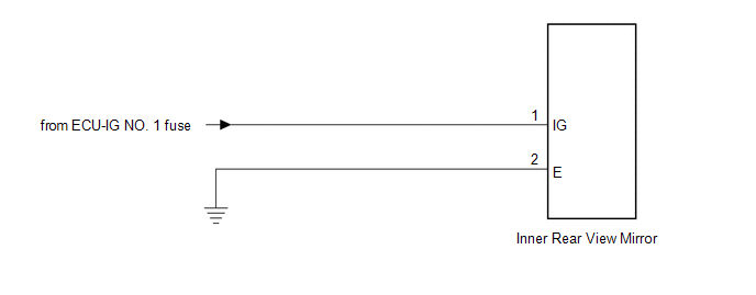
 Components
COMPONENTS
ILLUSTRATION
...
 Calibration
CALIBRATION
1. SELECT COMPASS DISPLAY MODE
(a) The AUTO switch allows selection of the compass display.
2. PERFORM CALIBRATION
(a) Because each vehicle has its own magnetic field, calibration shou ...
Other materials about Toyota Venza:
Installation
INSTALLATION
PROCEDURE
1. INSTALL POWER DISTRIBUTION
(a) Connect the 3 connectors.
(b) Engage the 2 claws to temporarily install the power distribution
as shown in the illustration.
...
Pressure Control Solenoid "A" Electrical (Shift Solenoid Valve SL1) (P0748)
DESCRIPTION
Changing from 1st to 6th is performed by the TCM turning shift solenoid valves
SL1, SL2, SL3, SL4 and SL on and off. If an open or short circuit occurs in any
of the shift solenoid valves, the TCM controls the remaining normal shift solenoid
...
Inspection
INSPECTION
PROCEDURE
1. INSPECT FRONT DIFFERENTIAL CASE
(a) Using SST, rotate the front differential side gear as shown in the
illustration.
SST: 09528-52010
09528-05030
Standard:
The front differential side gear does not lock wh ...

0.1409