Toyota Venza: Removal
REMOVAL
PROCEDURE
1. PRECAUTION
CAUTION:
Be sure to read Precaution thoroughly before servicing (See page
.gif) ).
).
NOTICE:
After turning the ignition switch off, waiting time may be required before disconnecting
the cable from the negative (-) battery terminal. Therefore, make sure to read the
disconnecting the cable from the negative (-) battery terminal notices before proceeding
with work (See page ).
2. DISCONNECT CABLE FROM NEGATIVE BATTERY TERMINAL
CAUTION:
Wait at least 90 seconds after disconnecting the cable from the negative (-) battery terminal to disable the SRS system.
NOTICE:
When disconnecting the cable, some systems need to be initialized after the cable
is reconnected (See page ).
3. REMOVE LOWER NO. 3 STEERING WHEEL COVER
|
(a) Disengage the claw and guide to remove the lower No. 3 steering wheel cover. |
|
4. REMOVE LOWER NO. 2 STEERING WHEEL COVER
|
(a) Disengage the claw and guide to remove the lower No. 2 steering wheel cover. |
|
5. REMOVE STEERING PAD
CAUTION:
When storing the steering pad, keep the airbag deployment side facing upward.
(a) Check that the ignition switch is off.
(b) Check that the cable is disconnected from the negative (-) battery terminal.
CAUTION:
Wait at least 90 seconds after disconnecting the cable from the negative (-) battery terminal to disable the SRS system.
|
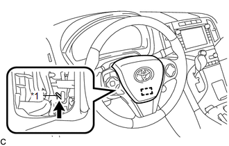
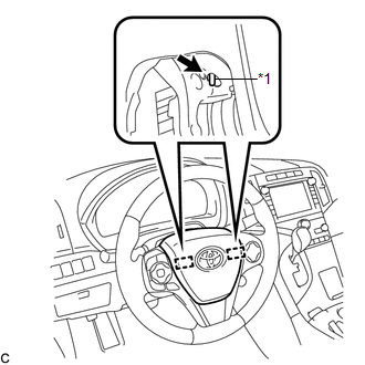
(c) Using a screwdriver, push up the torsion spring to disengage the pin. Text in Illustration
HINT: Insert the screwdriver from the installation hole of the lower No. 3 steering wheel cover. |
|
|
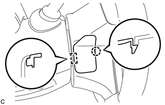
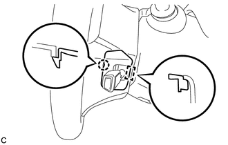
(d) Using a screwdriver, push in the 2 torsion springs to disengage the 2 pins. Text in Illustration
NOTICE: Do not drop the steering pad. HINT: Insert the screwdriver from the installation holes in the lower No. 3 steering wheel cover and lower No. 2 steering wheel cover. |
|
(e) Pull out the steering pad from the steering wheel assembly and support the steering pad with one hand.
NOTICE:
When removing the steering pad, do not pull the airbag wire harness.
|
(f) Disconnect the horn connector from the steering pad. |
|
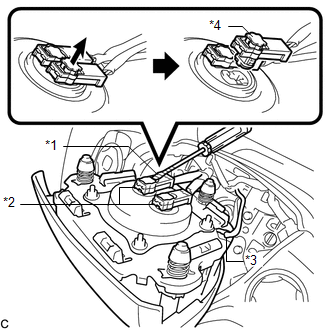
(g) Using a screwdriver with its tip wrapped with protective tape, release the 2 airbag connector locks.
Text in Illustration|
*1 |
Protective Tape |
|
*2 |
Airbag Connector |
|
*3 |
Horn Connector |
|
*4 |
Airbag Connector Lock |
(h) Disconnect the 2 airbag connectors to remove the steering pad.
NOTICE:
When disconnecting any airbag connector, take care not to damage the airbag wire harness.
 Installation
INSTALLATION
PROCEDURE
1. INSTALL STEERING PAD
(a) Check that the ignition switch is off.
(b) Check that the cable is disconnected from the negative (-) battery terminal.
CAUTION:
Wait at least ...
 Disposal
DISPOSAL
CAUTION / NOTICE / HINT
CAUTION:
Before performing pre-disposal deployment of any SRS part, review and closely
follow all applicable environmental and hazardous material regulations. Pre ...
Other materials about Toyota Venza:
Inspection
INSPECTION
PROCEDURE
1. INSPECT CYLINDER HEAD SUB-ASSEMBLY
(a) Using a precision straightedge and feeler gauge, measure the warpage of the
contact surfaces where the cylinder head contacts the cylinder block and manifold.
Maximum Warpage:
...
Removal
REMOVAL
PROCEDURE
1. PRECAUTION
CAUTION:
Be sure to read Precaution thoroughly before servicing (See page
).
NOTICE:
After turning the ignition switch off, waiting time may be required before disconnecting
the cable from the negative (-) battery term ...
System Diagram
SYSTEM DIAGRAM
Communication Table
Sender
Receiver
Signal
Line
Main Body ECU
(Driver Side Junction Block Assembly)
Clearance Warning ECU Assembly
Destination information
...

0.1148