Toyota Venza: System Diagram
SYSTEM DIAGRAM
 Communication Table
|
Transmitting ECU (Transmitter) |
Receiving ECU (Receiver) |
Signal |
Line |
|---|---|---|---|
|
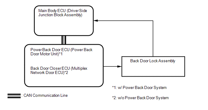
Main body ECU (Driver side junction block assembly) |
Power Back Door ECU (Power Back door motor unit)*1 Back Door Closer ECU (Multiplex Network Door ECU)*2 |
Power back door control signal |
CAN |
- *1: w/ Power Back Door System
- *2: w/o Power Back Door System
 System Description
SYSTEM DESCRIPTION
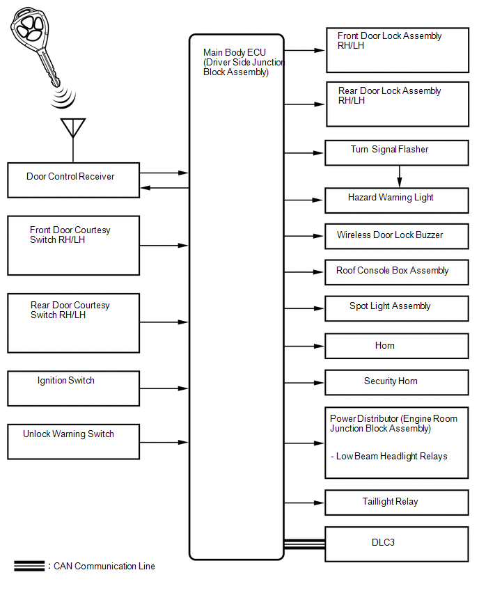
1. WIRELESS DOOR LOCK CONTROL SYSTEM
The wireless door lock control system functions to lock and unlock all the doors
from a distance. The system is controlled by a door control ...
 How To Proceed With Troubleshooting
CAUTION / NOTICE / HINT
HINT:
The wireless door lock control system troubleshooting procedures are
based on the premise that the power door lock control system is operating
normally. ...
Other materials about Toyota Venza:
Removal
REMOVAL
CAUTION / NOTICE / HINT
HINT:
Use the same procedure for the RH side and LH side.
The procedure listed below is for the LH side.
PROCEDURE
1. PRECAUTION
HINT:
See page
2. DRAIN AUTOMATIC TRANSAXLE FLUID
HINT:
for U ...
System Diagram
SYSTEM DIAGRAM
Communication Table
Transmitting ECU
Receiving ECU
Signal
Communication Method
Power window regulator master switch assembly
Power window regulator motor assembly (for ...
VSC OFF Indicator Light Remains ON
DESCRIPTION
The skid control ECU is connected to the combination meter via CAN communication.
Pressing the VSC OFF switch turns off traction control and pressing and holding
this switch turns off traction and VSC controls. If VSC control is turned off, the ...

0.1584