Toyota Venza: Parts Location
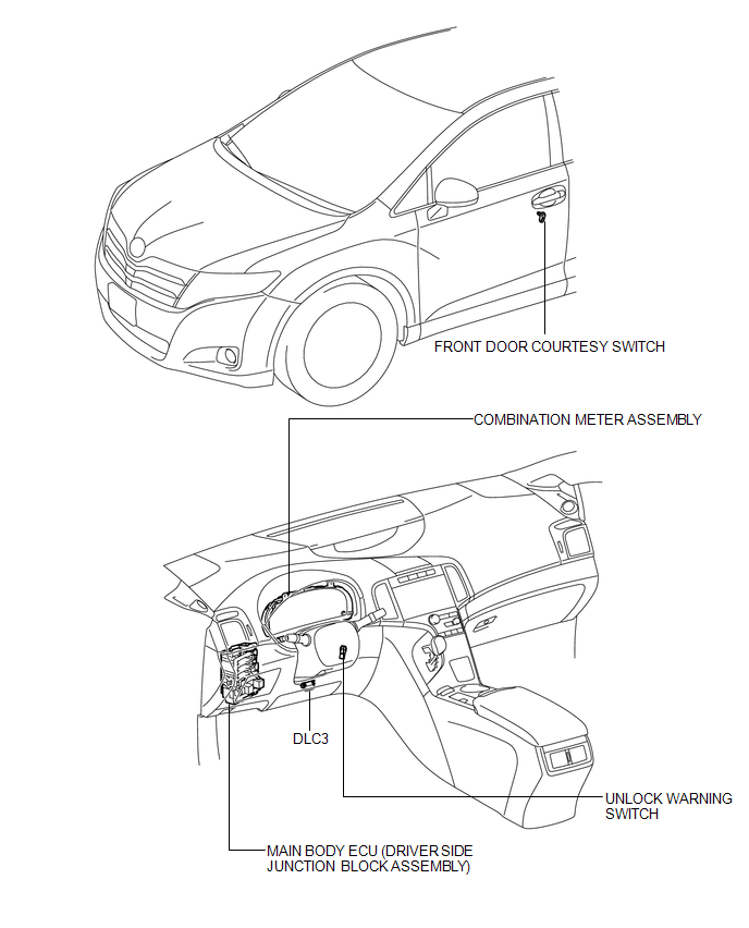
PARTS LOCATION
ILLUSTRATION
 Precaution
PRECAUTION
NOTICE:
When disconnecting the cable from the negative (-) battery terminal, initialize
the following systems after the cable is reconnected.
System Name
See Proc ...
 System Diagram
SYSTEM DIAGRAM
Communication Table
Sender
Receiver
Signal
Communication Method
Main Body ECU (Driver Side Junction Block Assembly)
...
Other materials about Toyota Venza:
Disassembly
DISASSEMBLY
PROCEDURE
1. REMOVE STEERING RACK BOOT CLIP (for LH Side)
(a) Using pliers, remove the steering rack boot clip.
2. REMOVE STEERING RACK BOOT CLIP (for RH Side)
HINT:
Perform the same procedure as for the LH side.
3. REMOVE NO. 2 STEERING RAC ...
Problem Symptoms Table
PROBLEM SYMPTOMS TABLE
HINT:
Use the table below to help determine the cause of problem symptoms.
If multiple suspected areas are listed, the potential causes of the symptoms
are listed in order of probability in the "Suspected Area" ...
Headlight Leveling ECU Power Source Circuit
DESCRIPTION
This circuit detects the state of the ignition switch, and sends it to the headlight
leveling ECU assembly.
WIRING DIAGRAM
CAUTION / NOTICE / HINT
NOTICE:
Inspect the fuses for circuits related to this system before performing the followin ...

0.1238