Toyota Venza: System Diagram
SYSTEM DIAGRAM
1. MIRROR CONTROL SYSTEM
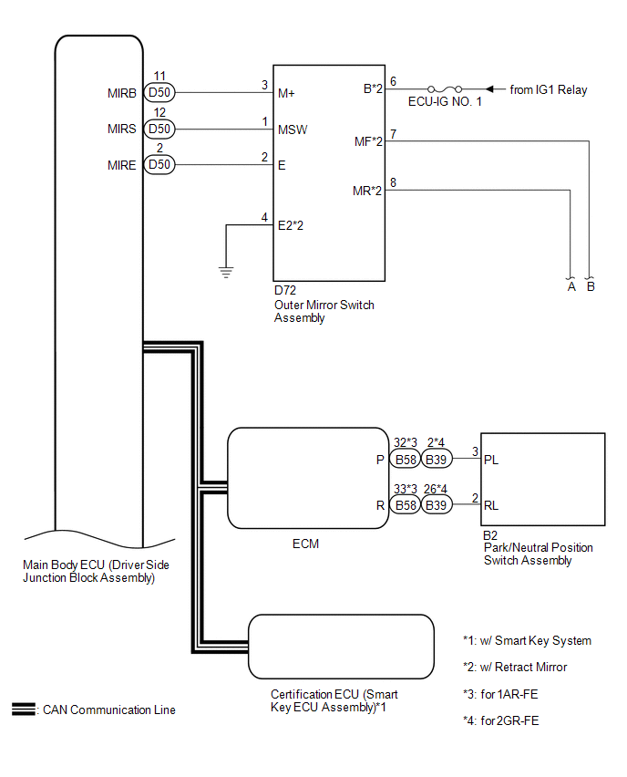
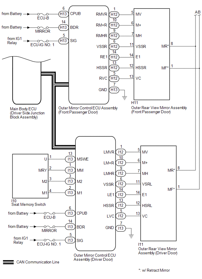 Communication Table
|
Sender |
Receiver |
Signal / Signal Condition |
Line |
|---|---|---|---|
|
Main body ECU (driver side junction block assembly) |
Outer mirror control ECU assembly (driver door) |
Ignition switch signal / ON or off |
CAN |
|
Main body ECU (driver side junction block assembly) |
Outer mirror control ECU assembly (front passenger door) |
Ignition switch signal / ON or off |
CAN |
|
Main body ECU (driver side junction block assembly) |
Outer mirror control ECU assembly (driver door) |
Ignition switch ACC signal / ACC or off |
CAN |
|
Main body ECU (driver side junction block assembly) |
Outer mirror control ECU assembly (front passenger door) |
Ignition switch ACC signal / ACC or off |
CAN |
|
Main body ECU (driver side junction block assembly) |
Outer mirror control ECU assembly (driver door) |
Outer mirror RH select switch signal / on or off |
CAN |
|
Main body ECU (driver side junction block assembly) |
Outer mirror control ECU assembly (front passenger door) |
Outer mirror RH select switch signal / on or off |
CAN |
|
Main body ECU (driver side junction block assembly) |
Outer mirror control ECU assembly (driver door) |
Outer mirror LH select switch signal / on or off |
CAN |
|
Main body ECU (driver side junction block assembly) |
Outer mirror control ECU assembly (front passenger door) |
Outer mirror LH select switch signal / on or off |
CAN |
|
Main body ECU (driver side junction block assembly) |
Outer mirror control ECU assembly (driver door) |
Mirror adjust switch signal (Right) / on or off |
CAN |
|
Main body ECU (driver side junction block assembly) |
Outer mirror control ECU assembly (front passenger door) |
Mirror adjust switch signal (Right) / on or off |
CAN |
|
Main body ECU (driver side junction block assembly) |
Outer mirror control ECU assembly (driver door) |
Mirror adjust switch signal (Left) / on or off |
CAN |
|
Main body ECU (driver side junction block assembly) |
Outer mirror control ECU assembly (front passenger door) |
Mirror adjust switch signal (Left) / on or off |
CAN |
|
Main body ECU (driver side junction block assembly) |
Outer mirror control ECU assembly (driver door) |
Mirror adjust switch signal (Up) / on or off |
CAN |
|
Main body ECU (driver side junction block assembly) |
Outer mirror control ECU assembly (front passenger door) |
Mirror adjust switch signal (Up) / on or off |
CAN |
|
Main body ECU (driver side junction block assembly) |
Outer mirror control ECU assembly (driver door) |
Mirror adjust switch signal (Down) / on or off |
CAN |
|
Main body ECU (driver side junction block assembly) |
Outer mirror control ECU assembly (front passenger door) |
Mirror adjust switch signal (Down) / on or off |
CAN |
|
Main body ECU (driver side junction block assembly) |
Outer mirror control ECU assembly (driver door) |
Mirror position request signal / memory request, reverse memory request, memory call request, reverse request or return request |
CAN |
|
Main body ECU (driver side junction block assembly) |
Outer mirror control ECU assembly (front passenger door) |
Mirror position request signal / memory request, reverse memory request, memory call request, reverse request or return request |
CAN |
|
Outer mirror control ECU assembly (driver door) |
Main body ECU (driver side junction block assembly) |
Outer mirror LH state signal / Manual operation, memory operation, reverse operation or return operation |
CAN |
|
Outer mirror control ECU assembly (front passenger door) |
Main body ECU (driver side junction block assembly) |
Outer mirror RH state signal / Manual operation, memory operation, reverse operation or return operation |
CAN |
|
Outer mirror control ECU assembly (driver door) |
Main body ECU (driver side junction block assembly) |
Seat memory switch signal / M1 switch, M2 switch or SET switch |
CAN |
2. MIRROR HEATER SYSTEM
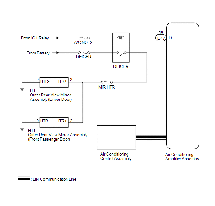 Communication Table
|
Transmitting ECU |
Receiving ECU |
Signal |
Communication Method |
|---|---|---|---|
|
Air Conditioning Control Assembly |
Air Conditioning Amplifier Assembly |
Rear window defogger switch signal |
LIN |
 System Description
SYSTEM DESCRIPTION
1. POWER MIRROR CONTROL SYSTEM DESCRIPTION
(a) This system has the following functions: power retract mirror function*,
reverse shift-linked function, electrical remote control ...
 How To Proceed With Troubleshooting
CAUTION / NOTICE / HINT
HINT:
Use the following procedure to troubleshoot the power mirror control
system.
*: Use the Techstream.
PROCEDURE
1.
VEHICLE ...
Other materials about Toyota Venza:
Drive Shaft System
Precaution
PRECAUTION
1. NOTICE OF REMOVING AND INSTALLING FRONT DRIVE SHAFT ASSEMBLY RH
(a) When removing and installing the front drive shaft assembly RH in a AWD vehicle,
be sure to first drain all the transaxle oil and transfer oil. If removal and i ...
Precaution
PRECAUTION
1. INITIALIZATION
NOTICE:
Perform the Registration (VIN registration) when replacing the ECM (See page
).
HINT:
Reset memory or initialization cannot be completed by only disconnecting and
reconnecting the cable of the negative (-) battery ...
Speed Signal Malfunction (B15C2)
DESCRIPTION
The navigation receiver assembly receives a vehicle speed signal from the combination
meter assembly and information from the navigation antenna assembly, and then adjusts
the vehicle position.
The navigation receiver assembly stores this DTC ...

0.1548