Toyota Venza: System Diagram
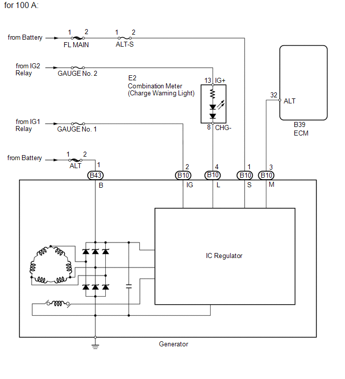
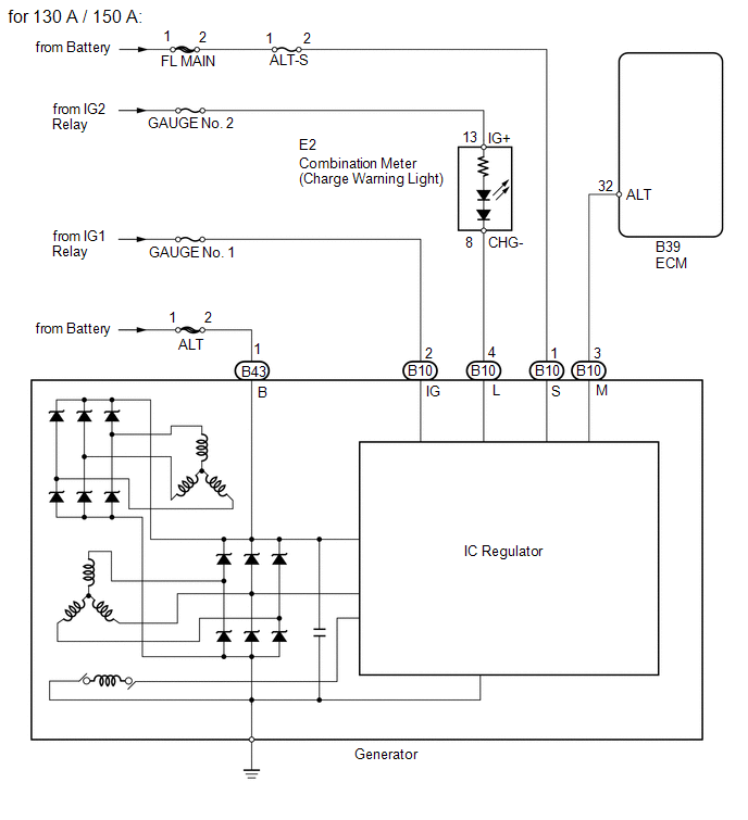
SYSTEM DIAGRAM
 Precaution
PRECAUTION
1. Check that the battery cables are connected to the correct terminals.
2. Disconnect the battery cables when the battery is given a quick charge.
3. Do not perform tests with a high vo ...
 Problem Symptoms Table
PROBLEM SYMPTOMS TABLE
Use the table below to help determine the cause of problem symptoms.
If multiple suspected areas are listed, the potential causes of the symptoms
are listed in o ...
Other materials about Toyota Venza:
Speed Signal Circuit
DESCRIPTION
The combination meter assembly receives the vehicle speed signal from this circuit.
The wheel speed sensors produce an output that varies according to the vehicle speed.
The wheel speed sensor output is received by the skid control ECU which u ...
Installation
INSTALLATION
CAUTION / NOTICE / HINT
HINT:
Use the same procedure for the RH side and LH side.
The procedure listed below is for the LH side.
PROCEDURE
1. INSTALL CURTAIN SHIELD AIRBAG ASSEMBLY
(a) Check that the ignition switch is off. ...
Short in Front Pretensioner Squib LH Circuit (B1905/74-B1908/74)
DESCRIPTION
The front pretensioner squib LH circuit consists of the center airbag sensor
assembly and front seat outer belt assembly LH.
The center airbag sensor assembly uses this circuit to deploy the seat belt pretensioner
when deployment conditions a ...

0.1608