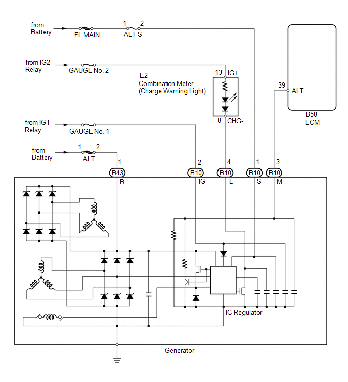
Toyota Venza: System Diagram
SYSTEM DIAGRAM
 Parts Location
PARTS LOCATION
ILLUSTRATION
ILLUSTRATION
...
 On-vehicle Inspection
ON-VEHICLE INSPECTION
PROCEDURE
1. CHECK BATTERY CONDITION
NOTICE:
If the battery is weak or if the engine is difficult to start, perform the following
procedure.
(a) Check the battery for dama ...
Other materials about Toyota Venza:
Camshaft Position "A" Actuator Circuit (Bank 1) (P0010)
DESCRIPTION
The Variable Valve Timing (VVT) system adjusts the intake valve timing to improve
driveability. The engine oil pressure turns the VVT controller to adjust the valve
timing.
The camshaft timing oil control valve assembly is a solenoid valve an ...
Washer Motor(for Front Side)
Components
COMPONENTS
ILLUSTRATION
Removal
REMOVAL
PROCEDURE
1. REMOVE FRONT WHEEL RH
2. REMOVE FRONT FENDER OUTSIDE MOULDING RH
HINT:
Use the same procedure for the RH side and LH side (See page
).
3. REMOVE FRONT FENDER LINER RH
...
Camshaft Position Sensor "B" Circuit (Bank 1) (P0365,P0367,P0368)
DESCRIPTION
The camshaft position sensor (EV signal sensor) for the exhaust camshaft consists
of a magnet and MRE (Magneto Resistance Element).
The exhaust camshaft has a timing rotor for the camshaft position sensor. When
the camshaft rotates, changes o ...

0.196