Toyota Venza: Parts Location
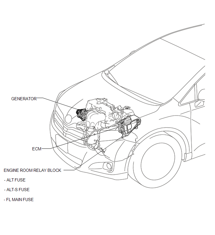
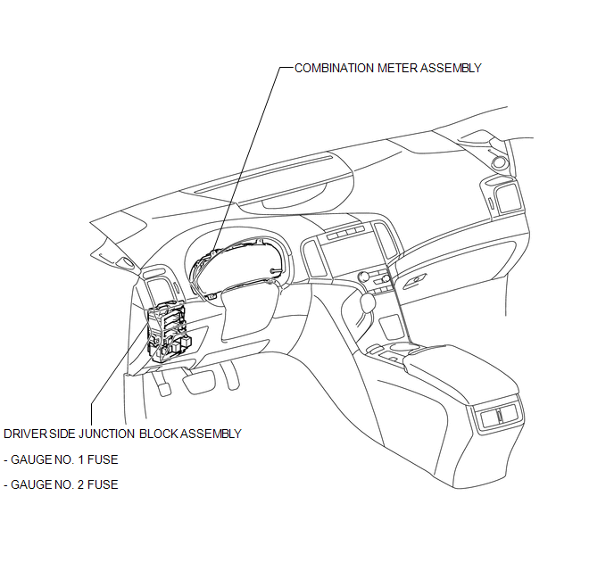
PARTS LOCATION
ILLUSTRATION
ILLUSTRATION
 Precaution
PRECAUTION
1. Check that the battery cables are connected to the correct terminals.
2. Disconnect the battery cables when the battery is given a quick charge.
3. Do not perform tests with a high vo ...
 System Diagram
SYSTEM DIAGRAM
...
Other materials about Toyota Venza:
Data Signal Circuit between Radio Receiver and Stereo Jack Adapter
DESCRIPTION
The No. 1 stereo jack adapter assembly sends the sound data signal or image data
signal from a USB device to the radio and display receiver assembly via this circuit.
WIRING DIAGRAM
PROCEDURE
1.
CHECK HARNESS AND CONN ...
Headlight Beam Level Control Actuator Circuit
DESCRIPTION
The headlight leveling ECU assembly actuates the headlight leveling motor according
to vehicle conditions.
WIRING DIAGRAM
PROCEDURE
1.
READ VALUE USING TECHSTREAM
(a) Connect the Techstream to the DLC3.
(b) ...
High Temperature Adjustment
HIGH TEMPERATURE ADJUSTMENT
PROCEDURE
1. ADJUST FLUID LEVEL AT HIGH TEMPERATURE
CAUTION:
Use caution while the engine is idling and the cooling fan is operating.
Be careful not to burn yourself when the automatic transaxle fluid temperature ...

0.1485