Toyota Venza: Removal
REMOVAL
PROCEDURE
1. REMOVE AIR CONDITIONING UNIT ASSEMBLY
(See page .gif) )
)
2. REMOVE NO. 1 FINISH PANEL MOUNTING BRACKET
3. REMOVE NO. 2 FINISH PANEL MOUNTING BRACKET
4. REMOVE NO. 3 AIR DUCT SUB-ASSEMBLY
5. REMOVE NO. 2 AIR DUCT SUB-ASSEMBLY
6. REMOVE AIR CONDITIONING HARNESS ASSEMBLY
7. REMOVE COOLER EXPANSION VALVE
8. REMOVE BLOWER ASSEMBLY WITH COOLER EVAPORATOR SUB-ASSEMBLY
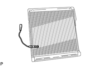
9. REMOVE COOLER EVAPORATOR SUB-ASSEMBLY
10. REMOVE NO. 1 COOLER THERMISTOR
|
(a) Remove the No. 1 cooler thermistor. |
|
 Components
COMPONENTS
ILLUSTRATION
ILLUSTRATION
...
 Inspection
INSPECTION
PROCEDURE
1. INSPECT EVAPORATOR TEMPERATURE SENSOR
(a) Measure the resistance according to the value(s) in the table below.
Standard Resistance:
Tester Connection
...
Other materials about Toyota Venza:
Removal
REMOVAL
PROCEDURE
1. REMOVE NO. 1 ENGINE COVER SUB-ASSEMBLY
2. REMOVE CAMSHAFT TIMING OIL CONTROL VALVE ASSEMBLY (for Exhaust Side)
(a) Disconnect the oil control valve connector.
(b) Remove the ...
Diagnostic Trouble Code Chart
DIAGNOSTIC TROUBLE CODE CHART
CAN Communication System
DTC Code
Detection Item
Output ECU/Techstream Display
See page
U0100
Lost Communication with ECM / PCM
Power management ...
System Diagram
SYSTEM DIAGRAM
Communication Table
Transmitting ECU (Transmitter)
Receiving ECU (Receiver)
Signal
Communication Method
Certification ECU (smart key ECU assembly)
Power management contro ...

0.1592