Toyota Venza: Reassembly
REASSEMBLY
PROCEDURE
1. INSTALL SHIFT LOCK CONTROL COMPUTER SUB-ASSEMBLY
|
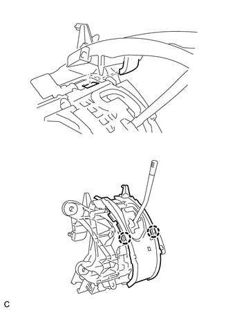
(a) Engage the 3 claws to install the shift lock control computer sub-assembly. |
|
.png)
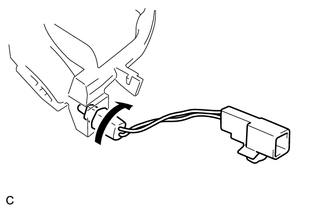
(b) Connect the connector.
2. INSTALL LOWER POSITION INDICATOR HOUSING
|
(a) Put the guide in position and engage the 2 claws to install the lower position indicator housing to the shift lock control unit assembly. NOTICE: Make sure that the claws are firmly engaged. |
|
3. INSTALL NO. 2 POSITION INDICATOR SLIDE COVER
(a) Install the No. 2 position indicator slide cover to the position indicator slide cover.
4. INSTALL POSITION INDICATOR SLIDE COVER
|
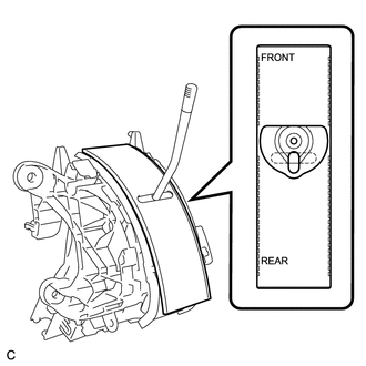
(a) Install the position indicator slide cover to the lower position indicator housing as shown in the illustration. |
|
5. INSTALL UPPER POSITION INDICATOR HOUSING
|
(a) Engage the 4 claws to install the upper position indicator housing to the lower position indicator housing. NOTICE: Make sure that the claws are firmly engaged. |
|
.png)
6. INSTALL POSITION INDICATOR LIGHT BULB
(a) Install the position indicator light bulb to the indicator light wire sub-assembly.
(b) Install the position indicator light cap to the position indicator light bulb.
7. INSTALL INDICATOR LIGHT WIRE SUB-ASSEMBLY
|
(a) Install the indicator light wire socket and connector to the position indicator light guide. |
|
8. INSTALL SHIFT LOCK RELEASE BUTTON
|
(a) Engage the 2 claws to install the shift lock release button and compression spring to the lower position indicator housing. NOTICE: Make sure that the claws are firmly engaged. |
|
.png)
9. INSTALL POSITION INDICATOR LIGHT GUIDE
|
(a) Engage the 4 claws to install the position indicator connector and position indicator light guide to the lower position indicator housing. NOTICE: Make sure that the claws are firmly engaged. |
|
.png)
10. INSTALL POSITION INDICATOR HOUSING SUB-ASSEMBLY
|
(a) Engage the 4 claws to install the position indicator housing sub-assembly to the lower position indicator housing. NOTICE: Make sure that the claws are firmly engaged. |
|
.png)
(b) Install the shift lever cap to the position indicator housing sub-assembly.
 Installation
INSTALLATION
PROCEDURE
1. INSTALL SHIFT LEVER ASSEMBLY
NOTICE:
Check that the park/neutral position switch and the shift lever are in neutral.
(a) Slide the slider of the transmission ...
 Speed Sensor(when Not Using The Engine Support Bridge)
Components
COMPONENTS
ILLUSTRATION
Removal
REMOVAL
PROCEDURE
1. REMOVE AUTOMATIC TRANSAXLE ASSEMBLY
HINT:
See the steps from "Remove Engine Assembly with transaxle" through &qu ...
Other materials about Toyota Venza:
Removal
REMOVAL
PROCEDURE
1. PRECAUTION
NOTICE:
After turning the ignition switch off, waiting time may be required before disconnecting
the cable from the negative (-) battery terminal. Therefore, make sure to read the
disconnecting the cable from the negativ ...
Diagnosis System
DIAGNOSIS SYSTEM
1. ECUS OR SENSORS WHICH COMMUNICATE THROUGH CAN COMMUNICATION SYSTEM
(a) CAN No. 1 Bus
(1) ECM
(2) Main body ECU (Driver side junction block)
(3) Combination meter
(4) Power steering ECU
(5) Air conditioning amplifier*3
(6) Center air ...
Precaution
PRECAUTION
1. BASIC REPAIR HINT
(a) HINTS ON OPERATIONS
1
Attire
Always wear a clean uniform.
A hat and safety shoes must be worn.
2
Vehicle protection
Prep ...

0.1344