Toyota Venza: Reassembly
REASSEMBLY
PROCEDURE
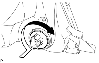
1. INSTALL FRONT SIDE MARKER LIGHT BULB
(a) Install the front side marker light bulb to the front side marker light socket.
|
(b) Turn the front side marker light socket with the front side marker light bulb in the direction indicated by the arrow shown in the illustration to install them as a unit. |
|
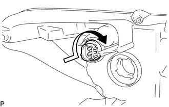
2. INSTALL FRONT TURN SIGNAL LIGHT BULB
(a) Install the front turn signal light bulb to the front turn signal light socket.
(b) for Halogen Headlight:
|
(1) Turn the front turn signal light socket with the front turn signal light bulb in the direction indicated by the arrow shown in the illustration to install them as a unit. |
|
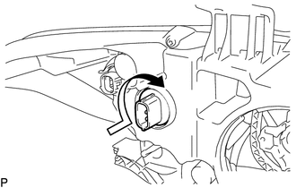
(c) for HID Headlight:
|
(1) Turn the front turn signal light socket with the front turn signal light bulb in the direction indicated by the arrow shown in the illustration to install them as a unit. |
|
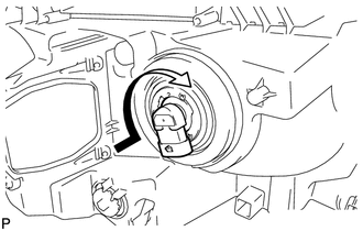
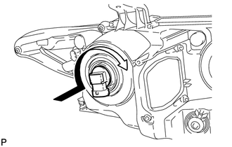
3. INSTALL NO. 1 HEADLIGHT BULB (for Halogen Headlight)
|
(a) Turn the No. 1 headlight bulb in the direction indicated by the arrow shown in the illustration to install it. NOTICE: Do not touch the bulb glass. |
|
4. INSTALL NO. 2 HEADLIGHT BULB (for Halogen Headlight)
|
(a) Turn the No. 2 headlight bulb in the direction indicated by the arrow shown in the illustration to install it. NOTICE: Do not touch the bulb glass. |
|
5. INSTALL DISCHARGE HEADLIGHT BULB (for HID Headlight)
(a) Set the discharge headlight bulb to the headlight unit.
NOTICE:
Do not touch the bulb glass.
|
(b) Lock the set spring to install the discharge headlight bulb as shown in the illustration. |
|
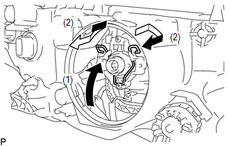
6. INSTALL LIGHT CONTROL ECU (for HID Headlight)
|
(a) Turn the socket of the light control ECU in the direction indicated by the arrow shown in the illustration to connect it. NOTICE:
|
|
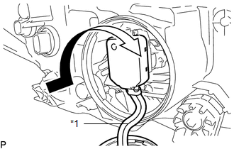
(b) Check that the red line on the output harness is not twisted and store the harness in the headlight assembly securely so that the output harness is not pinched.
Text in Illustration|
*1 |
Red Line |
|
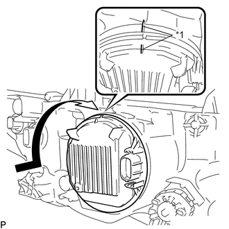
(c) Turn the light control ECU in the direction indicated by the arrow shown in the illustration until the lock marks are aligned to install it. Text in Illustration
NOTICE:
|
|
 Adjustment
ADJUSTMENT
CAUTION / NOTICE / HINT
HINT:
It is possible that a bulb is incorrectly installed, affecting headlight aim.
Bulb installation should be considered prior to performing the adjustment pr ...
 Installation
INSTALLATION
PROCEDURE
1. INSTALL HEADLIGHT ASSEMBLY
(a) Connect each connector.
(b) Install the headlight assembly with the bolt and 3 screws.
Torque:
3.6 N·m {37 kgf·cm, 32 in·lbf}
2. INS ...
Other materials about Toyota Venza:
Trip information
Display items can be switched by pressing the “INFO” button.
- Average Fuel Economy
Displays the average fuel consumption since the function was reset.
• The function can be reset by pressing and holding the “SELECT RESET” button
when the ...
Diagnosis System
DIAGNOSIS SYSTEM
1. DESCRIPTION
(a) Lighting system data can be read from the Data Link Connector 3 (DLC3) of
the vehicle. When the system seems to be malfunctioning, use the Techstream to check
for malfunctions and perform repairs.
2. CHECK DLC3
(a) C ...
Precaution
PRECAUTION
1. INITIALIZATION
NOTICE:
Perform the Registration (VIN registration) when replacing the ECM (See page
).
HINT:
Reset memory or initialization cannot be completed by only disconnecting and
reconnecting the cable of the negative (-) battery ...

0.1393