Toyota Venza: Side Turn Signal Light Assembly
Components
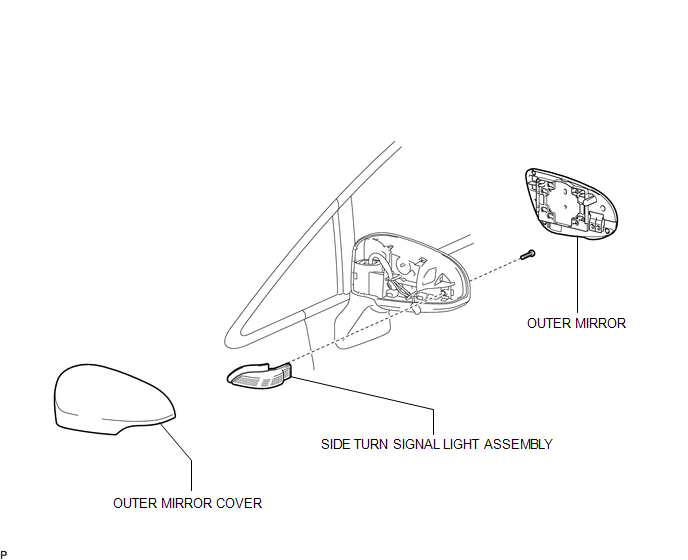
COMPONENTS
ILLUSTRATION
Removal
REMOVAL
CAUTION / NOTICE / HINT
HINT:
- Use the same procedure for the RH and LH sides.
- The procedure described below is for the LH side.
PROCEDURE
1. REMOVE OUTER MIRROR
.gif)
2. REMOVE OUTER MIRROR COVER
3. REMOVE SIDE TURN SIGNAL LIGHT ASSEMBLY
|
(a) Remove the screw. |
|
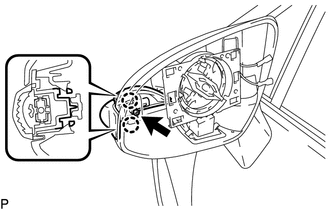
(b) Disengage the 2 claws.
(c) Disconnect the connector and remove the side turn signal light assembly.
Inspection
INSPECTION
PROCEDURE
1. INSPECT SIDE TURN SIGNAL LIGHT ASSEMBLY LH
|
(a) Connect a positive (+) lead from the battery to terminal 1 and a negative (-) lead to terminal 2. |
|
.png)
(b) Check that the side turn signal light comes on.
OK:
The light comes on.
Text in Illustration|
*1 |
Component without harness connected (Side Turn Signal Light Assembly LH) |
If the result is not as specified, replace the side turn signal light assembly LH.
2. INSPECT SIDE TURN SIGNAL LIGHT ASSEMBLY RH
|
(a) Connect a positive (+) lead from the battery to terminal 1 and a negative (-) lead to terminal 2. |
|
(b) Check that the side turn signal light comes on.
OK:
The light comes on.
Text in Illustration|
*1 |
Component without harness connected (Side Turn Signal Light Assembly RH) |
If the result is not as specified, replace the side turn signal light assembly RH.
Installation
INSTALLATION
CAUTION / NOTICE / HINT
HINT:
- Use the same procedure for the RH and LH sides.
- The procedure described below is for the LH side.
PROCEDURE
1. INSTALL SIDE TURN SIGNAL LIGHT ASSEMBLY
(a) Connect the connector.
(b) Engage the 2 claws.
(c) Install the side turn signal light assembly with the screw.
2. INSTALL OUTER MIRROR COVER
.gif)
3. INSTALL OUTER MIRROR
 Relay
Relay
On-vehicle Inspection
ON-VEHICLE INSPECTION
PROCEDURE
1. INSPECT TAILLIGHT RELAY (TAIL)
(a) Remove the taillight relay from the main body ECU (driver side junction
block assembly) ...
 Stop Light Switch
Components
COMPONENTS
ILLUSTRATION
Removal
REMOVAL
PROCEDURE
1. REMOVE STOP LIGHT SWITCH ASSEMBLY
(a) Disconnect the connector.
...
Other materials about Toyota Venza:
Installation
INSTALLATION
CAUTION / NOTICE / HINT
HINT:
Use the same procedure for the RH side and LH side.
The procedure listed below is for the LH side.
PROCEDURE
1. SECURE REAR SHOCK ABSORBER WITH COIL SPRING
2. INSTALL REAR LOWER COIL SPRING ...
Removal
REMOVAL
PROCEDURE
1. REMOVE NO. 1 SLIDING ROOF GLASS SUB-ASSEMBLY
(a) Fully open the No. 2 sliding roof glass sub-assembly.
(b) Using a T20 "TORX" socket wrench, remove the 6 screws and No. 1 sliding
roof glass sub-assembly.
...
Cellular Phone Registration Failure
PROCEDURE
1.
CHECK USAGE CONDITION
(a) Check that the vehicle and cellular phone meet the following conditions:
NOTICE:
If changing cellular phone settings, updating software, etc. is necessary, make
sure to obtain the per ...

0.1471