Toyota Venza: Stop Light Switch
Components
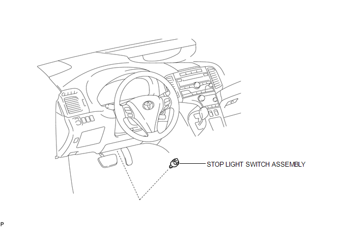
COMPONENTS
ILLUSTRATION
Removal
REMOVAL
PROCEDURE
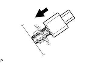
1. REMOVE STOP LIGHT SWITCH ASSEMBLY
|
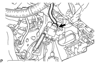
(a) Disconnect the connector. |
|
|
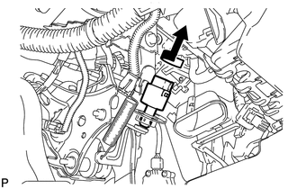
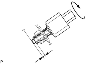
(b) Turn the stop light switch assembly counterclockwise and remove the stop light switch assembly. |
|
Inspection
INSPECTION
PROCEDURE
1. INSPECT STOP LIGHT SWITCH ASSEMBLY
(a) Measure the resistance according to the value(s) in the table below.
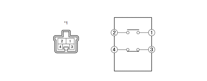
Standard Resistance:
|
Tester Connection |
Switch Condition |
Specified Condition |
|---|---|---|
|
1 - 2 |
Pushed |
10 kΩ or higher |
|
Not pushed |
Below 1 Ω |
|
|
3 - 4 |
Pushed |
Below 1 Ω |
|
Not pushed |
10 kΩ or higher |
|
*1 |
Component without harness connected (Stop Light Switch Assembly) |
If the result is not as specified, replace the stop light switch assembly.
Installation
INSTALLATION
PROCEDURE
1. INSTALL STOP LIGHT SWITCH ASSEMBLY
|
(a) Insert the stop light switch assembly until the rod hits the pedal. NOTICE: When inserting the stop light switch assembly, support the pedal from behind so that the pedal is not depressed. |
|
|
(b) Make a quarter turn clockwise to install the stop light switch assembly. Torque: 1.5 N·m {15 kgf·cm, 13 in·lbf} or less NOTICE: When inserting the stop light switch assembly, support the pedal from behind so that the pedal is not depressed. |
|
(c) Connect the connector.
(d) Check the protrusion of the rod.
Protrusion of the rod:
1.5 to 2.5 mm (0.0591 to 0.0984 in.)
If the protrusion is not as specified, adjust it.
NOTICE:
Do not depress the brake pedal.
 Side Turn Signal Light Assembly
Components
COMPONENTS
ILLUSTRATION
Removal
REMOVAL
CAUTION / NOTICE / HINT
HINT:
Use the same procedure for the RH and LH sides.
The procedure described below is for the LH si ...
 Turn Signal Flasher Assembly
Components
COMPONENTS
ILLUSTRATION
Inspection
INSPECTION
PROCEDURE
1. INSPECT TURN SIGNAL FLASHER ASSEMBLY
(a) Disconnect the D34 turn signal flasher assembly connector.
...
Other materials about Toyota Venza:
Stereo Jack Adapter Assembly
Components
COMPONENTS
ILLUSTRATION
Removal
REMOVAL
PROCEDURE
1. REMOVE UPPER CONSOLE PANEL SUB-ASSEMBLY (w/o Seat Heater System)
2. REMOVE UPPER CONSOLE PANEL SUB-ASSEMBLY (w/ Seat Heater System)
3. REMOVE NO. 2 CONSOLE BOX CARPET
4. RE ...
Antenna Coil Open / Short (B2784)
DESCRIPTION
This DTC is stored when there is an open or short in the transponder key coil
(built into the engine switch).
DTC No.
DTC Detection Condition
Trouble Area
B2784
Transponder key coil i ...
Diagnostic Trouble Code Chart
DIAGNOSTIC TROUBLE CODE CHART
If a trouble code is displayed during the DTC check, check the parts listed for
that code in the table below and proceed to the appropriate page.
HINT:
The steering lock ECU does not store DTCs regarding the past problems.
S ...

0.1491