Toyota Venza: Front Stabilizer Bar(when Not Using The Engine Support Bridge For Awd)
Components
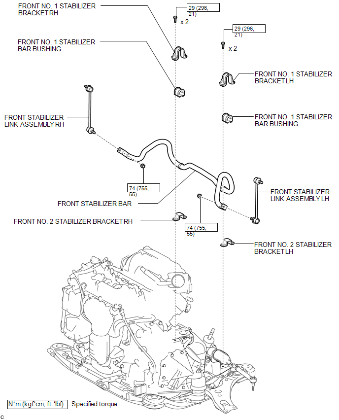
COMPONENTS
ILLUSTRATION
Inspection
INSPECTION
PROCEDURE
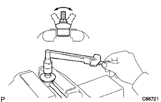
1. INSPECT FRONT STABILIZER LINK ASSEMBLY
|
(a) Inspect the turning torque of the ball joint. (1) Secure the front stabilizer link assembly in a vise using aluminum plates. (2) Install the nut to the front stabilizer link assembly stud. (3) Using a torque wrench, turn the nut continuously at a rate of 3 to 5 seconds per turn and take the torque reading on the 5th turn. Turning torque: 0.05 to 1.96 N*m (0.5 to 20 kgf*cm, 0.4 to 17 in.*lbf) If the turning torque is not within the specified range, replace the front stabilizer link assembly with a new one. |
|
(b) Inspect the dust cover.
(1) Check that the dust cover is not cracked and that there is no grease on it.
Removal
REMOVAL
PROCEDURE
1. REMOVE ENGINE ASSEMBLY WITH TRANSAXLE
for 1AR-FE: (See page .gif) )
)
for 2GR-FE: (See page )
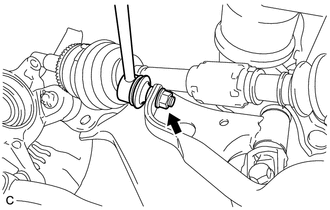
2. SEPARATE FRONT STABILIZER LINK ASSEMBLY LH
|
(a) Remove the nut and separate the front stabilizer link assembly LH. HINT: If the ball joint turns together with the nut, use a hexagon wrench (6 mm) to hold the stud bolt. |
|
3. SEPARATE FRONT STABILIZER LINK ASSEMBLY RH
HINT:
Perform the same procedure as for the LH side.
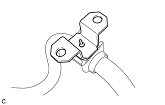
4. REMOVE FRONT NO. 1 STABILIZER BRACKET LH
|
(a) Remove the 2 bolts and front No. 1 stabilizer bracket LH from the front frame assembly. |
|
.png)
5. REMOVE FRONT NO. 1 STABILIZER BRACKET RH
HINT:
Perform the same procedure as for the LH side.
6. REMOVE FRONT STABILIZER BAR
7. REMOVE FRONT NO. 2 STABILIZER BRACKET LH
|
(a) Remove the front No. 2 stabilizer bracket LH from the front stabilizer bar bushing. |
|
8. REMOVE FRONT NO. 2 STABILIZER BRACKET RH
HINT:
Perform the same procedure as for the LH side.
9. REMOVE FRONT NO. 1 STABILIZER BAR BUSHING
(a) Remove the 2 front No. 1 stabilizer bar bushings from the front stabilizer bar.
Installation
INSTALLATION
PROCEDURE
1. INSTALL FRONT NO. 1 STABILIZER BAR BUSHING
|
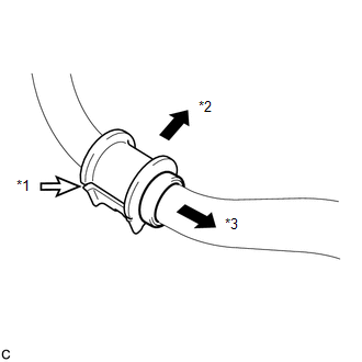
(a) Install the 2 front No. 1 stabilizer bar bushings to the front stabilizer bar as shown in the illustration. Text in Illustration
NOTICE: When installing the front No. 1 stabilizer bar bushings, make sure that the cutout faces the rear of the vehicle. |
|
2. INSTALL FRONT NO. 2 STABILIZER BRACKET LH
|
(a) Install the front No. 2 stabilizer bracket LH to the front No. 1 stabilizer bar bushing. |
|
.png)
3. INSTALL FRONT NO. 2 STABILIZER BRACKET RH
HINT:
Perform the same procedure as for the LH side.
4. INSTALL FRONT STABILIZER BAR
(a) Install the front stabilizer bar to the front frame assembly.
5. INSTALL FRONT NO. 1 STABILIZER BRACKET LH
|
(a) Install the front No. 1 stabilizer bracket LH to the front frame assembly with the 2 bolts. Torque: 29 N·m {296 kgf·cm, 21 ft·lbf} |
|
.png)
6. INSTALL FRONT NO. 1 STABILIZER BRACKET RH
HINT:
Perform the same procedure as for the LH side.
7. INSTALL FRONT STABILIZER LINK ASSEMBLY LH
|
(a) Install the front stabilizer link assembly LH with the nut. Torque: 74 N·m {755 kgf·cm, 55 ft·lbf} HINT: If the ball joint turns together with the nut, use a hexagon wrench (6 mm) to hold the stud bolt. |
|
.png)
8. INSTALL FRONT STABILIZER LINK ASSEMBLY RH
HINT:
Perform the same procedure as for the LH side.
9. INSTALL ENGINE ASSEMBLY WITH TRANSAXLE
for 1AR-FE: (See page .gif) )
)
for 2GR-FE: (See page )
 Installation
INSTALLATION
CAUTION / NOTICE / HINT
HINT:
Use the same procedure for the LH side and RH side.
The following procedure listed below is for the LH side.
PROCEDURE
1. SECURE FRONT ...

Other materials about Toyota Venza:
Selecting trailer ball
Use the correct trailer ball for your application.
1. Trailer ball load rating
Matches or exceeds the gross trailer weight rating of the trailer.
2. Ball diameter
Matches the size of the trailer coupler. Most couplers are stamped with the required
trai ...
Disassembly
DISASSEMBLY
PROCEDURE
1. REMOVE MAGNETIC SWITCH ASSEMBLY
(a) Remove the nut and disconnect the lead wire from the magnetic switch.
(b) Remove the 2 screws holding the magnetic switch to t ...
Customize Parameters
CUSTOMIZE PARAMETERS
PROCEDURE
1. CUSTOMIZE INTUITIVE PARKING ASSIST SYSTEM
(a) Customizing with the Techstream
NOTICE:
When the customer requests a change in a function, first make sure that
the function can be customized.
Be sure to make ...

0.1145