Toyota Venza: Short in Side Squib LH Circuit (B1825/56-B1828/56)
DESCRIPTION
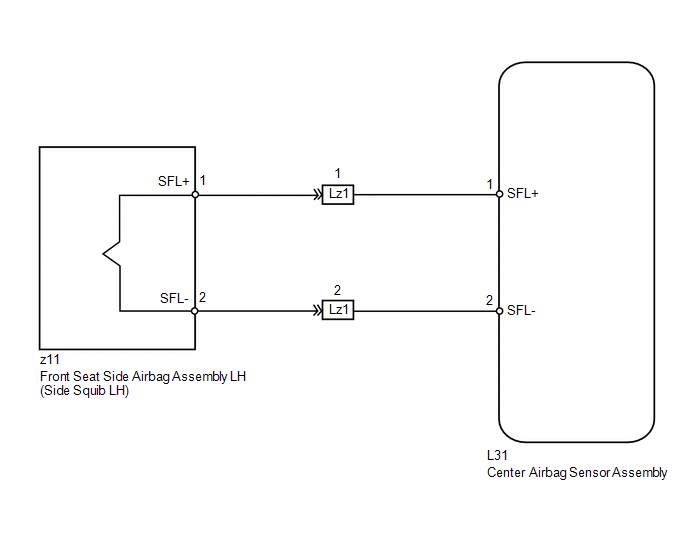
The side squib LH circuit consists of the center airbag sensor assembly and front seat side airbag assembly LH.
The center airbag sensor assembly uses this circuit to deploy the airbag when deployment conditions are met.
These DTCs are stored when a malfunction is detected in the side squib LH circuit.
|
DTC No. |
DTC Detection Condition |
Trouble Area |
|---|---|---|
|
B1825/56 |
|
|
|
B1826/56 |
|
|
|
B1827/56 |
|
|
|
B1828/56 |
|
|
WIRING DIAGRAM
CAUTION / NOTICE / HINT
HINT:
- Perform the simulation method by selecting check mode (Signal Check)
using the Techstream (See page
.gif) ).
).
- After selecting check mode (Signal Check), perform the simulation method
by wiggling each connector of the airbag system or driving the vehicle on
a city or rough road (See page ).
PROCEDURE
|
1. |
CHECK CONNECTORS |
|
(a) Turn the ignition switch off. |
|
(b) Disconnect the cable from the negative (-) battery terminal, and wait for at least 90 seconds.
(c) Check that the connectors are properly connected to the front seat side airbag assembly LH and center airbag sensor assembly.
OK:
The connectors are properly connected.
HINT:
If the connectors are not connected securely, reconnect the connectors and proceed to the next inspection.
(d) Disconnect the connectors from the front seat side airbag assembly LH and center airbag sensor assembly.
(e) Check that the terminals of the connectors are not damaged.
OK:
The terminals are not deformed or damaged.
(f) Check that the short spring for the floor wire with the activation prevention mechanism is not deformed or damaged.
OK:
The short spring is not deformed or damaged.
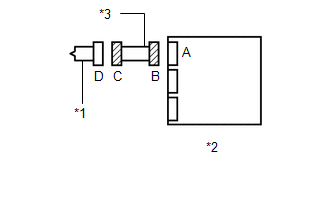
Text in Illustration|
*1 |
Side squib LH |
|
*2 |
Center Airbag Sensor Assembly |
|
*3 |
Floor Wire |
| NG | .gif) |
REPLACE FLOOR WIRE |
|
.gif)
|
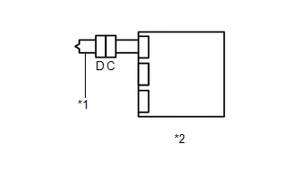
2. |
CHECK FRONT SEAT SIDE AIRBAG ASSEMBLY LH (SIDE SQUIB LH) |
|
(a) Connect the connector to the center airbag sensor assembly. |
|
(b) Connect SST (resistance 2.1 Ω) to connector C.
CAUTION:
Never connect an electrical tester to the front seat side airbag assembly LH (side squib LH) for measurement, as this may lead to a serious injury due to airbag deployment.
NOTICE:
- Do not forcibly insert SST into the terminals of the connector when connecting.
- Insert SST straight into the terminals of the connector.
SST: 09843-18061
(c) Connect the cable to the negative (-) battery terminal.
(d) Turn the ignition switch to ON, and wait for at least 60 seconds.
(e) Clear the DTCs stored in memory (See page
).
(f) Turn the ignition switch off.
(g) Turn the ignition switch to ON, and wait for at least 60 seconds.
(h) Check for DTCs (See page ).
OK:
DTC B1825, B1826, B1827, B1828 or 56 is not output.
HINT:
Codes other than DTCs B1825, B1826, B1827, B1828 and 56 may be output at this time, but they are not related to this check.
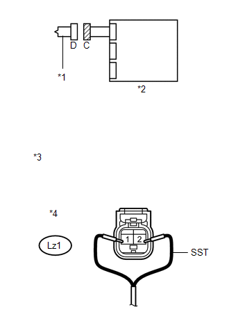
Text in Illustration|
*1 |
Side squib LH |
|
*2 |
Center Airbag Sensor Assembly |
|
*3 |
Front view of wire harness connector (to Front Seat Side Airbag Assembly LH) |
|
*4 |
Connector C |
| OK | |
REPLACE FRONT SEAT SIDE AIRBAG ASSEMBLY LH |
|
|
3. |
CHECK FLOOR WIRE (SIDE SQUIB LH CIRCUIT) |
(a) Turn the ignition switch off.
(b) Disconnect the cable from the negative (-) battery terminal, and wait for at least 90 seconds.
(c) Disconnect SST from connector C.
(d) Disconnect the floor wire from the center airbag sensor assembly.
(e) Check for a short to B+ in the circuit.
(1) Connect the cable to the negative (-) battery terminal.
(2) Turn the ignition switch to ON.
(3) Measure the voltage according to the value(s) in the table below.
Standard Voltage:
|
Tester Connection |
Switch Condition |
Specified Condition |
|---|---|---|
|
Lz1-1 (SFL+) - Body ground |
Ignition switch ON |
Below 1 V |
|
Lz1-2 (SFL-) - Body ground |
Ignition switch ON |
Below 1 V |
(f) Check for an open in the circuit.
(1) Turn the ignition switch off.
(2) Disconnect the cable from the negative (-) battery terminal, and wait for at least 90 seconds.
(3) Measure the resistance according to the value(s) in the table below.
Standard Resistance:
|
Tester Connection |
Condition |
Specified Condition |
|---|---|---|
|
Lz1-1 (SFL+) - Lz1-2 (SFL-) |
Always |
Below 1 Ω |
(g) Check for a short to ground in the circuit.
(1) Measure the resistance according to the value(s) in the table below.
Standard Resistance:
|
Tester Connection |
Condition |
Specified Condition |
|---|---|---|
|
Lz1-1 (SFL+) - Body ground |
Always |
1 MΩ or higher |
|
Lz1-2 (SFL-) - Body ground |
Always |
1 MΩ or higher |
(h) Check for a short in the circuit.
(1) Release the activation prevention mechanism built into connector B (See page
).
(2) Measure the resistance according to the value(s) in the table below.
Standard Resistance:
|
Tester Connection |
Condition |
Specified Condition |
|---|---|---|
|
Lz1-1 (SFL+) - Lz1-2 (SFL-) |
Always |
1 MΩ or higher |
|
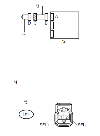
*1 |
Side squib LH |
|
*2 |
Center Airbag Sensor Assembly |
|
*3 |
Floor Wire |
|
*4 |
Front view of wire harness connector (to Front Seat Side Airbag Assembly LH) |
|
*5 |
Connector C |
| NG | |
REPLACE FLOOR WIRE |
|
|
4. |
CHECK CENTER AIRBAG SENSOR ASSEMBLY |
|
(a) Restore the released activation prevention mechanism of connector B to the original condition. |
|
(b) Connect the connectors to the front seat side airbag assembly LH and center airbag sensor assembly.
(c) Connect the cable to the negative (-) battery terminal.
(d) Turn the ignition switch to ON, and wait for at least 60 seconds.
(e) Clear the DTCs stored in memory (See page
).
(f) Turn the ignition switch off.
(g) Turn the ignition switch to ON, and wait for at least 60 seconds.
(h) Check for DTCs (See page ).
OK:
DTC B1825, B1826, B1827, B1828 or 56 is not output.
Text in Illustration|
*1 |
Side squib LH |
|
*2 |
Center Airbag Sensor Assembly |
HINT:
Codes other than DTCs B1825, B1826, B1827, B1828 and 56 may be output at this time, but they are not related to this check.
| OK | |
USE SIMULATION METHOD TO CHECK |
| NG | |
REPLACE CENTER AIRBAG SENSOR ASSEMBLY |
 Short in Side Squib RH Circuit (B1820/55-B1823/55)
DESCRIPTION
The side squib RH circuit consists of the center airbag sensor assembly and front
seat side airbag assembly RH.
The center airbag sensor assembly uses this circuit to deploy the airbag ...
 Short in Curtain Shield Squib RH Circuit (B1830/57-B1833/57)
DESCRIPTION
The curtain shield squib RH circuit consists of the center airbag sensor assembly
and curtain shield airbag assembly RH.
The center airbag sensor assembly uses this circuit to deploy t ...
Other materials about Toyota Venza:
Ignition Switch Circuit
DESCRIPTION
The main body ECU (driver side junction block assembly) determines the ignition
switch position (OFF, ACC, ON) based on signals from the IG or ACC circuit.
WIRING DIAGRAM
PROCEDURE
1.
READ VALUE USING TECHSTREAM
...
Inspection
INSPECTION
PROCEDURE
1. INSPECT THROTTLE BODY ASSEMBLY
Text in Illustration
*1
Component without harness connected
(Throttle Body)
(a) Check that the throttle valve opens and closes smoothly.
(b) Check that there is no ...
Display does not Dim when Light Control Switch is Turned ON
PROCEDURE
1.
CHECK IMAGE QUALITY SETTING
(a) Turn the light control switch to the tail or head position.
(b) Check that the daytime screen setting on the display adjustment screen is
set to on.
Result
...

0.1778