Toyota Venza: Short in Curtain Shield Squib RH Circuit (B1830/57-B1833/57)
DESCRIPTION
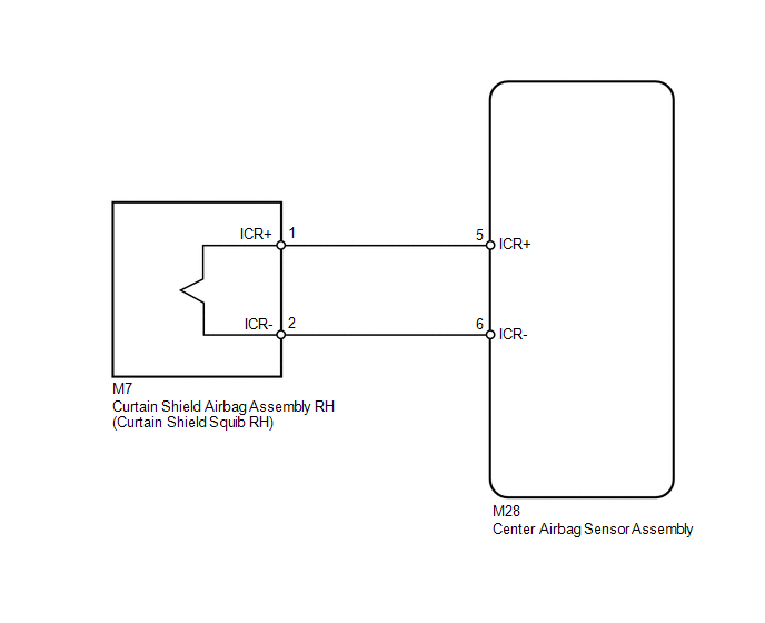
The curtain shield squib RH circuit consists of the center airbag sensor assembly and curtain shield airbag assembly RH.
The center airbag sensor assembly uses this circuit to deploy the airbag when deployment conditions are met.
These DTCs are stored when a malfunction is detected in the curtain shield squib RH circuit.
|
DTC No. |
DTC Detection Condition |
Trouble Area |
|---|---|---|
|
B1830/57 |
|
|
|
B1831/57 |
|
|
|
B1832/57 |
|
|
|
B1833/57 |
|
|
WIRING DIAGRAM
CAUTION / NOTICE / HINT
HINT:
- Perform the simulation method by selecting check mode (Signal Check)
using the Techstream (See page
.gif) ).
).
- After selecting check mode (Signal Check), perform the simulation method
by wiggling each connector of the airbag system or driving the vehicle on
a city or rough road (See page ).
PROCEDURE
|
1. |
CHECK CONNECTORS |
|
(a) Turn the ignition switch off. |
|
.png)
(b) Disconnect the cable from the negative (-) battery terminal, and wait for at least 90 seconds.
(c) Check that the connectors are properly connected to the curtain shield airbag assembly RH and center airbag sensor assembly.
OK:
The connectors are properly connected.
HINT:
If the connectors are not connected securely, reconnect the connectors and proceed to the next inspection.
(d) Disconnect the connectors from the curtain shield airbag assembly RH and center airbag sensor assembly.
(e) Check that the terminals of the connectors are not damaged.
OK:
The terminals are not deformed or damaged.
(f) Check that the No. 2 floor wire connector (on the curtain shield airbag assembly RH side) is not damaged.
OK:
The lock button is not disengaged, and the claw of the lock is not deformed or damaged.
(g) Check that the short spring for the No. 2 floor wire with the activation prevention mechanism is not deformed or damaged.
OK:
The short spring is not deformed or damaged.
Text in Illustration|
*1 |
Curtain Shield Squib RH |
|
*2 |
Center Airbag Sensor Assembly |
|
*3 |
No. 2 Floor Wire |
| NG | .gif) |
REPLACE NO. 2 FLOOR WIRE |
|
.gif)
|
2. |
CHECK CURTAIN SHIELD AIRBAG ASSEMBLY RH (CURTAIN SHIELD RH SQUIB) |
|
(a) Connect the connector to the center airbag sensor assembly. |
|
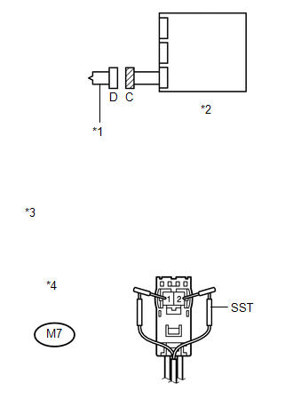
(b) Connect SST (resistance 2.1 Ω) to connector C.
CAUTION:
Never connect an electrical tester to the curtain shield airbag assembly RH (curtain shield squib RH) for measurement, as this may lead to a serious injury due to airbag deployment.
NOTICE:
- Do not forcibly insert SST into the terminals of the connector when connecting.
- Insert SST straight into the terminals of the connector.
SST: 09843-18061
(c) Connect the cable to the negative (-) battery terminal.
(d) Turn the ignition switch to ON, and wait for at least 60 seconds.
(e) Clear the DTCs stored in memory (See page
).
(f) Turn the ignition switch off.
(g) Turn the ignition switch to ON, and wait for at least 60 seconds.
(h) Check for DTCs (See page ).
OK:
DTC B1830, B1831, B1832, B1833 or 57 is not output.
Text in Illustration|
*1 |
Curtain Shield Squib RH |
|
*2 |
Center Airbag Sensor Assembly |
|
*3 |
Front view of wire harness connector (to Curtain Shield Airbag Assembly RH) |
|
*4 |
Connector C |
HINT:
Codes other than DTCs B1830, B1831, B1832, B1833 and 57 may be output at this time, but they are not related to this check.
| OK | |
REPLACE CURTAIN SHIELD AIRBAG ASSEMBLY RH |
|
|
3. |
CHECK NO. 2 FLOOR WIRE (CURTAIN SHIELD SQUIB RH CIRCUIT) |
|
(a) Turn the ignition switch off. |
|
(b) Disconnect the cable from the negative (-) battery terminal, and wait for at least 90 seconds.
(c) Disconnect SST from connector C.
(d) Disconnect the No. 2 floor wire from the center airbag sensor assembly.
(e) Check for a short to B+ in the circuit.
(1) Connect the cable to the negative (-) battery terminal.
(2) Turn the ignition switch to ON.
(3) Measure the voltage according to the value(s) in the table below.
Standard Voltage:
|
Tester Connection |
Switch Condition |
Specified Condition |
|---|---|---|
|
M7-1 (ICR+) - Body ground |
Ignition switch ON |
Below 1 V |
|
M7-2 (ICR-) - Body ground |
Ignition switch ON |
Below 1 V |
(f) Check for an open in the circuit.
(1) Turn the ignition switch off.
(2) Disconnect the cable from the negative (-) battery terminal, and wait for at least 90 seconds.
(3) Measure the resistance according to the value(s) in the table below.
Standard Resistance:
|
Tester Connection |
Condition |
Specified Condition |
|---|---|---|
|
M7-1 (ICR+) - M7-2 (ICR-) |
Always |
Below 1 Ω |
(g) Check for a short to ground in the circuit.
(1) Measure the resistance according to the value(s) in the table below.
Standard Resistance:
|
Tester Connection |
Condition |
Specified Condition |
|---|---|---|
|
M7-1 (ICR+) - Body ground |
Always |
1 MΩ or higher |
|
M7-2 (ICR-) - Body ground |
Always |
1 MΩ or higher |
(h) Check for a short in the circuit.
(1) Release the activation prevention mechanism built into connector B (See page
).
(2) Measure the resistance according to the value(s) in the table below.
Standard Resistance:
|
Tester Connection |
Condition |
Specified Condition |
|---|---|---|
|
M7-1 (ICR+) - M7-2 (ICR-) |
Always |
1 MΩ or higher |
|
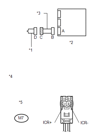
*1 |
Curtain Shield Squib RH |
|
*2 |
Center Airbag Sensor Assembly |
|
*3 |
No. 2 Floor Wire |
|
*4 |
Front view of wire harness connector (to Curtain Shield Airbag Assembly RH) |
|
*5 |
Connector C |
| NG | |
REPLACE NO. 2 FLOOR WIRE |
|
|
4. |
CHECK CENTER AIRBAG SENSOR ASSEMBLY |
|
(a) Restore the released activation prevention mechanism of connector B to the original condition. |
|
.png)
(b) Connect the connectors to the curtain shield airbag assembly RH and center airbag sensor assembly.
(c) Connect the cable to the negative (-) battery terminal.
(d) Turn the ignition switch to ON, and wait for at least 60 seconds.
(e) Clear the DTCs stored in memory (See page
).
(f) Turn the ignition switch off.
(g) Turn the ignition switch to ON, and wait for at least 60 seconds.
(h) Check for DTCs (See page ).
OK:
DTC B1830, B1831, B1832, B1833 or 57 is not output.
Text in Illustration|
*1 |
Curtain Shield Squib RH |
|
*2 |
Center Airbag Sensor Assembly |
HINT:
Codes other than DTCs B1830, B1831, B1832, B1833 and 57 may be output at this time, but they are not related to this check.
| OK | |
USE SIMULATION METHOD TO CHECK |
| NG | |
REPLACE CENTER AIRBAG SENSOR ASSEMBLY |
 Short in Side Squib LH Circuit (B1825/56-B1828/56)
DESCRIPTION
The side squib LH circuit consists of the center airbag sensor assembly and front
seat side airbag assembly LH.
The center airbag sensor assembly uses this circuit to deploy the airbag ...
 Short in Curtain Shield Squib LH Circuit (B1835/58-B1838/58)
DESCRIPTION
The curtain shield squib LH circuit consists of the center airbag sensor assembly
and curtain shield airbag assembly LH.
The center airbag sensor assembly uses this circuit to deploy t ...
Other materials about Toyota Venza:
Removal
REMOVAL
CAUTION / NOTICE / HINT
NOTICE:
If automatic transaxle assembly parts are replaced, refer to Parts Replacement
Compensation Table to determine if any additional operations are necessary (See
page ).
PROCEDURE
1. DISCHARGE FUEL PRESSURE
See p ...
Disassembly
DISASSEMBLY
PROCEDURE
1. REMOVE POSITION INDICATOR HOUSING SUB-ASSEMBLY
(a) Remove the shift lever cap from the position indicator housing sub-assembly.
(b) Disengage the 4 claws and remove the position indicator housing sub-assembly.
...
Disassembly
DISASSEMBLY
PROCEDURE
1. INSPECT CONNECTING ROD THRUST CLEARANCE
(a) Using a dial indicator, measure the thrust clearance while moving
the connecting rod back and forth.
Standard thrust clearance:
0.160 to 0.512 mm (0.00630 to 0.0202 i ...

0.1357