Toyota Venza: Inspection
INSPECTION
PROCEDURE
1. INSPECT THROTTLE BODY ASSEMBLY
 Text in Illustration
|
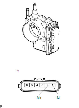
*1 |
Component without harness connected (Throttle Body) |
(a) Check that the throttle valve opens and closes smoothly.
(b) Check that there is no sludge accumulating around the throttle body.
(c) Measure the resistance according to the value(s) in the table below.
Standard Resistance:
|
Tester Connection |
Condition |
Specified Condition |
|---|---|---|
|
1 (M-) - 2 (M+) |
20°C (68°F) |
0.3 to 100 Ω |
If the result is not as specified, replace the throttle body assembly.
 On-vehicle Inspection
ON-VEHICLE INSPECTION
PROCEDURE
1. CHECK THROTTLE BODY ASSEMBLY
(a) Check the throttle control motor operating sounds.
(1) Turn the ignition switch to ON.
(2) When pressing the accelerator pedal, ...
 Removal
REMOVAL
PROCEDURE
1. REMOVE WINDSHIELD WIPER MOTOR AND LINK
(a) Remove the windshield wiper motor and link (See page
).
2. REMOVE OUTER COWL TOP PANEL SUB-ASSEMBLY
3. REMOVE NO. 1 ENGINE COV ...
Other materials about Toyota Venza:
4WD Control ECU Communication Stop Mode
DESCRIPTION
Detection Item
Symptom
Trouble Area
4WD Control ECU Communication Stop Mode
"Four Wheel Drive Control" is not displayed on the "CAN Bus
Check" screen ...
Removal
REMOVAL
CAUTION / NOTICE / HINT
HINT:
Use the same procedure for the RH side and LH side.
The procedure listed below is for the LH side.
PROCEDURE
1. REMOVE REAR WHEEL
2. REMOVE DECK SIDE TRIM
(a) Disengage the 5 claws, and ...
PBD Pulse Sensor Malfunction (B2222)
DESCRIPTION
A pulse sensor is built into the power back door ECU (power back door
motor unit) to detect foreign objects and the back door position. The pulse
sensor monitors the operating speed of the back door to detect foreign objects.
Th ...

0.1393