Toyota Venza: Ignition Switch Circuit
DESCRIPTION
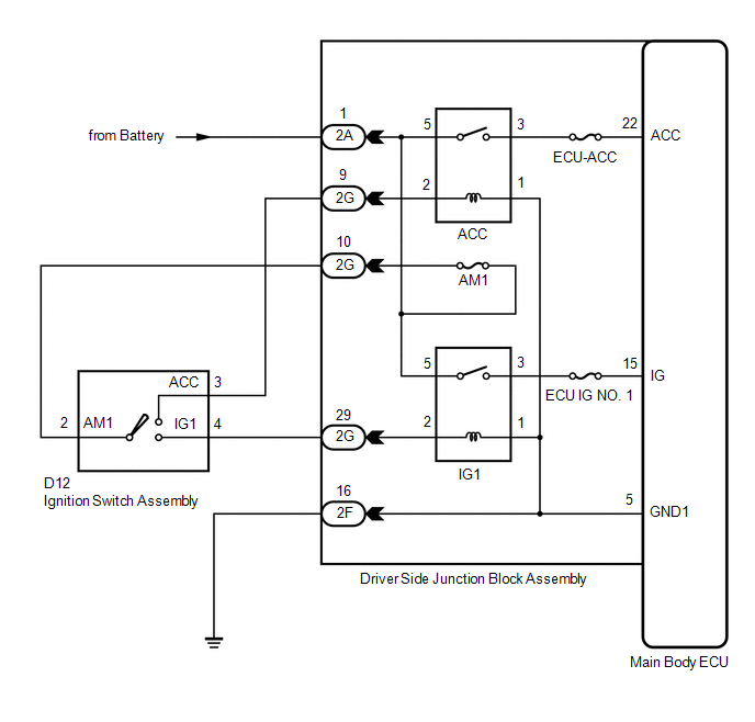
The main body ECU (driver side junction block assembly) determines the ignition switch position (OFF, ACC, ON) based on signals from the IG or ACC circuit.
WIRING DIAGRAM
PROCEDURE
|
1. |
READ VALUE USING TECHSTREAM |
(a) Connect the Techstream to the DLC3.
(b) Turn the ignition switch to ON.
(c) Turn the Techstream on.
(d) Select the items below in the Data List and read the display on the Techstream.
Main Body|
Tester Display |
Measurement Item/Range |
Normal Condition |
Diagnostic Note |
|---|---|---|---|
|
IG SW |
Ignition switch ON signal/ON or OFF |
ON: Ignition switch ON OFF: Ignition switch off |
- |
|
ACC SW |
Ignition switch ACC signal/ON or OFF |
ON: Ignition switch ACC OFF: Ignition switch off |
- |
OK:
When the ignition switch is operated, the display changes as shown in the table.
| OK | .gif) |
PROCEED TO NEXT SUSPECTED AREA SHOWN IN PROBLEM SYMPTOMS TABLE |
|
.gif)
|
2. |
CHECK HARNESS AND CONNECTOR (BATTERY - DRIVER SIDE JUNCTION BLOCK ASSEMBLY) |
|
(a) Disconnect the 2A driver side junction block assembly connector. |
|
(b) Measure the voltage according to the value(s) in the table below.
Standard Voltage:
|
Tester Connection |
Condition |
Specified Condition |
|---|---|---|
|
2A-1 - Body ground |
Ignition switch ON |
11 to 14 V |
|
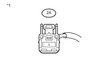
*1 |
Front view of wire harness connector (to Driver Side Junction Block Assembly) |
| NG | |
REPAIR OR REPLACE HARNESS OR CONNECTOR |
|
|
3. |
INSPECT IGNITION SWITCH ASSEMBLY |
|
(a) Remove the ignition switch assembly (See page
|
|
.gif) for 2GR-FE,
for 2GR-FE,
(b) Disconnect the D12 ignition switch assembly connector.
(c) Measure the resistance according to the value(s) in the table below.
Standard Resistance:
|
Tester Connection |
Condition |
Specified Condition |
|---|---|---|
|
D12-4 (IG1) - D12-2 (AM1) |
Ignition switch ON |
Below 1 Ω |
|
D12-3 (ACC) - D12-2 (AM1) |
Ignition switch ACC |
Below 1 Ω |
|
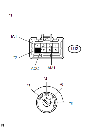
*1 |
Component without harness connected (Ignition Switch Assembly) |
|
*2 |
No Pin |
|
*3 |
LOCK |
|
*4 |
ACC |
|
*5 |
ON |
|
*6 |
START |
|
Result |
Proceed to |
|---|---|
|
OK |
A |
|
NG (for 2GR-FE) |
B |
|
NG (for 1AR-FE) |
C |
| B | |
REPLACE IGNITION SWITCH ASSEMBLY (for 2GR-FE) |
| C | |
REPLACE IGNITION SWITCH ASSEMBLY (for 1AR-FE) |
|
|
4. |
CHECK HARNESS AND CONNECTOR (DRIVER SIDE J/B - DRIVER SIDE J/B) |
|
(a) Disconnect the 2G driver side junction block assembly connector. |
|
(b) Measure the resistance according to the value(s) in the table below.
Standard Resistance:
|
Tester Connection |
Condition |
Specified Condition |
|---|---|---|
|
2G-10 - 2G-29 |
Ignition switch ON |
Below 1 Ω |
|
2G-10 - 2G-9 |
Ignition switch ACC |
Below 1 Ω |
|
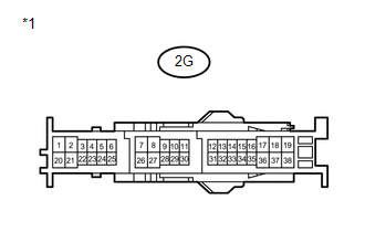
*1 |
Front view of wire harness connector (to Driver Side Junction Block Assembly) |
| NG | |
REPAIR OR REPLACE HARNESS OR CONNECTOR |
|
|
5. |
CHECK HARNESS AND CONNECTOR (DRIVER SIDE JUNCTION BLOCK ASSEMBLY - BODY GROUND) |
|
(a) Disconnect the 2F driver side junction block assembly connector. |
|
.png)
(b) Measure the resistance according to the value(s) in the table below.
Standard Resistance:
|
Tester Connection |
Condition |
Specified Condition |
|---|---|---|
|
2F-16 - Body ground |
Always |
Below 1 Ω |
|
*1 |
Front view of wire harness connector (to Driver Side Junction Block Assembly) |
| OK | |
REPLACE MAIN BODY ECU (DRIVER SIDE JUNCTION BLOCK ASSEMBLY) |
| NG | |
REPAIR OR REPLACE HARNESS OR CONNECTOR |
 Security Horn Circuit
DESCRIPTION
When the theft deterrent system is switched from the armed state to the alarm
sounding state, the main body ECU (driver side junction block assembly) controls
the security horn.
WIRI ...
 Security Indicator Light Circuit
DESCRIPTION
Even when the theft deterrent system is in the disarmed state, the security indicator
blinks due to a signal output from the immobiliser system. The security indicator
blinks continuo ...
Other materials about Toyota Venza:
Monitor Drive Pattern
MONITOR DRIVE PATTERN
1. TEST MONITOR DRIVE PATTERN FOR ECT
CAUTION:
Perform this drive pattern on a level surface and strictly observe the posted
speed limits and traffic laws while driving.
HINT:
Performing this drive pattern is one method to simulate ...
System Description
SYSTEM DESCRIPTION
1. SYSTEM DESCRIPTION
(a) The Electronic Controlled Automatic Transaxle (ECT) is an automatic transaxle
that has its shift timing electronically controlled by the Transmission Control
Module (TCM). The TCM detects electrical signals th ...
Speed Sensor Rotor Faulty (C1237/37,C1275/75-C1278/78)
DESCRIPTION
The skid control ECU measures the speed of each wheel by receiving signals from
the speed sensor.
These signals are used for recognizing that all four wheels are operating properly.
Therefore, all wheel signals must be equal.
DTCs C1275/75 to ...

0.1712