Toyota Venza: Horn Circuit
DESCRIPTION
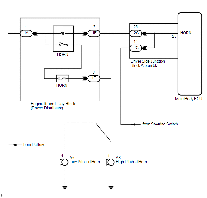
When the theft deterrent system is switched from the armed state to the alarm sounding state, the main body ECU (driver side junction block assembly) transmits a signal to cause the horn to sound at intervals of 0.4 seconds.
WIRING DIAGRAM
PROCEDURE
|
1. |
INSPECT HORNS |
(a) Press the horn switch and check if the horns sound.
|
Result |
Proceed to |
|---|---|
|
Horns sound |
A |
|
Horns do not sound |
B |
| B | .gif) |
GO TO HORN SYSTEM |
|
.gif)
|
2. |
PERFORM ACTIVE TEST USING TECHSTREAM |
(a) Connect the Techstream to the DLC3.
(b) Turn the ignition switch to ON.
(c) Turn the Techstream on.
(d) Select the item below in the Active Test and then check that the horns operate.
Main Body|
Tester Display |
Test Part |
Control Range |
Diagnostic Note |
|---|---|---|---|
|
Vehicle Horn |
Vehicle horns |
ON / OFF |
- |
OK:
The vehicle horns sound and stop correctly when operated through the Techstream.
| OK | |
PROCEED TO NEXT SUSPECTED AREA SHOWN IN PROBLEM SYMPTOMS TABLE |
| NG | |
REPLACE MAIN BODY ECU (DRIVER SIDE JUNCTION BLOCK ASSEMBLY) |
 Engine Hood Courtesy Switch Circuit
DESCRIPTION
The security courtesy switch is installed together with the hood lock. This switch
turns off when the engine hood is opened and turns on when the engine hood is closed.
WIRING DIAGRAM
...
 Security Horn Circuit
DESCRIPTION
When the theft deterrent system is switched from the armed state to the alarm
sounding state, the main body ECU (driver side junction block assembly) controls
the security horn.
WIRI ...
Other materials about Toyota Venza:
Removal
REMOVAL
PROCEDURE
1. ALIGN FRONT WHEELS FACING STRAIGHT AHEAD
2. DISCONNECT CABLE FROM NEGATIVE BATTERY TERMINAL
NOTICE:
When disconnecting the cable, some systems need to be initialized after the cable
is reconnected (See page ).
3. REMOVE FRONT WHEE ...
Random Access Memory (RAM) (P0604)
MONITOR DESCRIPTION
The ECM continuously monitors its internal memory status. This self-check ensures
that the ECM is functioning properly. It is diagnosed by internal "mirroring" of
the main CPU and sub CPU to detect Random Access Memory (RAM) ...
Screen Flicker or Color Distortion
PROCEDURE
1.
CHECK DISPLAY SETTING
(a) Reset display settings (contrast, brightness) and check that the screen appears
normal.
OK:
The display returns to normal.
OK
END
NG
...

0.1575