Toyota Venza: Seat Heater System
Precaution
PRECAUTION
1. NOTICE FOR INITIALIZATION
HINT:
When disconnecting the cable from the negative (-) battery terminal, initialize the following systems after the cable is reconnected.
|
System Name |
See procedure |
|---|---|
|
Back Door Closer System |
|
|
Power Back Door System |
.gif)
2. IGNITION SWITCH EXPRESSIONS
HINT:
The type of ignition switch used on this model differs according to the specifications of the vehicle. The expressions listed in the table below are used in this section.
|
Expression |
Ignition Switch (position) |
Engine Switch (condition) |
|---|---|---|
|
Ignition Switch off |
LOCK |
Off |
|
Ignition Switch ON |
ON |
On (IG) |
|
Ignition Switch ACC |
ACC |
On (ACC) |
|
Engine Start |
START |
Start |
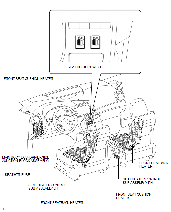
Parts Location
PARTS LOCATION
ILLUSTRATION
Problem Symptoms Table
PROBLEM SYMPTOMS TABLE
Seat Heater System|
Symptom |
Suspected Area |
See page |
|---|---|---|
|
Drivers seat heater does not warm up |
SEAT HTR fuse |
- |
|
Seat heater switch LH |
|
|
|
Front seat cushion heater (for power seat) |
|
|
|
Front seatback heater (for power seat) |
|
|
|
Seat heater controller |
- |
|
|
Wire harness or connector |
- |
|
|
Passengers seat heater does not warm up |
SEAT HTR fuse |
- |
|
Seat heater switch RH |
|
|
|
Front seat cushion heater (for power seat) |
|
|
|
Front seatback heater (for power seat) |
|
|
|
Seat heater controller |
- |
|
|
Wire harness or connector |
- |
.gif)
System Diagram
SYSTEM DIAGRAM
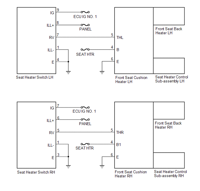
 Seat Heater Switch
Components
COMPONENTS
ILLUSTRATION
Removal
REMOVAL
PROCEDURE
1. REMOVE UPPER CONSOLE PANEL SUB-ASSEMBLY
2. REMOVE SEAT HEATER SWITCH
(a) Disengage the 2 claws and remove th ...
 Seat Memory Switch
Components
COMPONENTS
ILLUSTRATION
Removal
REMOVAL
PROCEDURE
1. REMOVE FRONT DOOR INSIDE HANDLE BEZEL PLUG LH
2. REMOVE POWER WINDOW REGULATOR MASTER SWITCH ASSEMBLY WITH FRONT DOOR AR ...
Other materials about Toyota Venza:
Electrical Key Oscillator(for Rear Side)
Components
COMPONENTS
ILLUSTRATION
Removal
REMOVAL
PROCEDURE
1. REMOVE REAR BUMPER PLATE LH
2. REMOVE REAR BUMPER PLATE RH
3. REMOVE REAR BUMPER ASSEMBLY
4. REMOVE ELECTRICAL KEY ANTENNA
(a) Disconnect the connector.
...
Removal
REMOVAL
CAUTION / NOTICE / HINT
PROCEDURE
1. PRECAUTION
NOTICE:
After turning the ignition switch off, waiting time may be required before disconnecting
the cable from the negative (-) battery terminal. Therefore, make sure to read the
disconnecting t ...
Removal
REMOVAL
CAUTION / NOTICE / HINT
CAUTION:
Some of these service operations affect the SRS airbag system. Read the precautionary
notices concerning the SRS airbag system before servicing the steering column (See
page ).
PROCEDURE
1. PRECAUTION
HINT:
...

0.1516