Toyota Venza: Vanity Light
Components
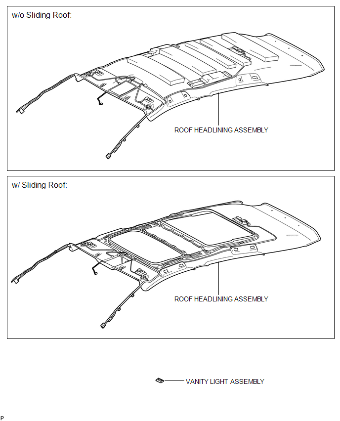
COMPONENTS
ILLUSTRATION
Installation
INSTALLATION
PROCEDURE
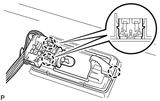
1. INSTALL VANITY LIGHT ASSEMBLY
|
(a) Engage the 3 claws and install the vanity light assembly. |
|
2. INSTALL ROOF HEADLINING ASSEMBLY
HINT:
Refer to the procedure from Install Roof Headlining Assembly (See page
.gif) ).
).
Removal
REMOVAL
PROCEDURE
1. REMOVE ROOF HEADLINING ASSEMBLY
HINT:
Refer to the procedure up to Remove Roof Headlining Assembly (See page
.gif) ).
).
2. REMOVE VANITY LIGHT ASSEMBLY
|
(a) Tilt the tab to disengage the 2 claws <A> and separate the bulb holder from the vanity light, as shown in the illustration. Text in Illustration
|
|
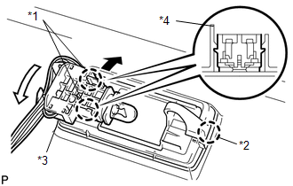
(b) Disengage the claw <B> and remove the vanity light assembly.
 Room Light
Components
COMPONENTS
ILLUSTRATION
Removal
REMOVAL
PROCEDURE
1. REMOVE SPOT LIGHT ASSEMBLY
(a) Using a screwdriver with its tip wrapped with protective tape, disengage
the ...

Other materials about Toyota Venza:
Installation
INSTALLATION
PROCEDURE
1. INSTALL FRONT DRIVE SHAFT ASSEMBLY LH
(a) Align the splines of the shaft and install the drive shaft assembly
LH using a brass bar and a hammer.
NOTICE:
Set the shaft snap ring with the opening fac ...
Fail-safe Chart
FAIL-SAFE CHART
1. FAIL-SAFE FUNCTION
If the following malfunctions occur, the AWD control ECU will stop the
function of 4WD control system or partly change the function to control
the system.
If a malfunction occurs in the senso ...
Installation
INSTALLATION
CAUTION / NOTICE / HINT
HINT:
Use the same procedure for the LH side and RH side.
The following procedure is for the LH side.
If the sensor rotor needs to be replaced, replace it together with the
front drive shaft assembly. ...

0.1485